


Reference Manual
00809-0100-4665, Rev AA
August 2010
6-9
Rosemount 8732
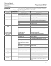
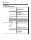
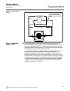
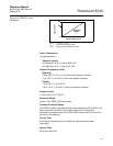
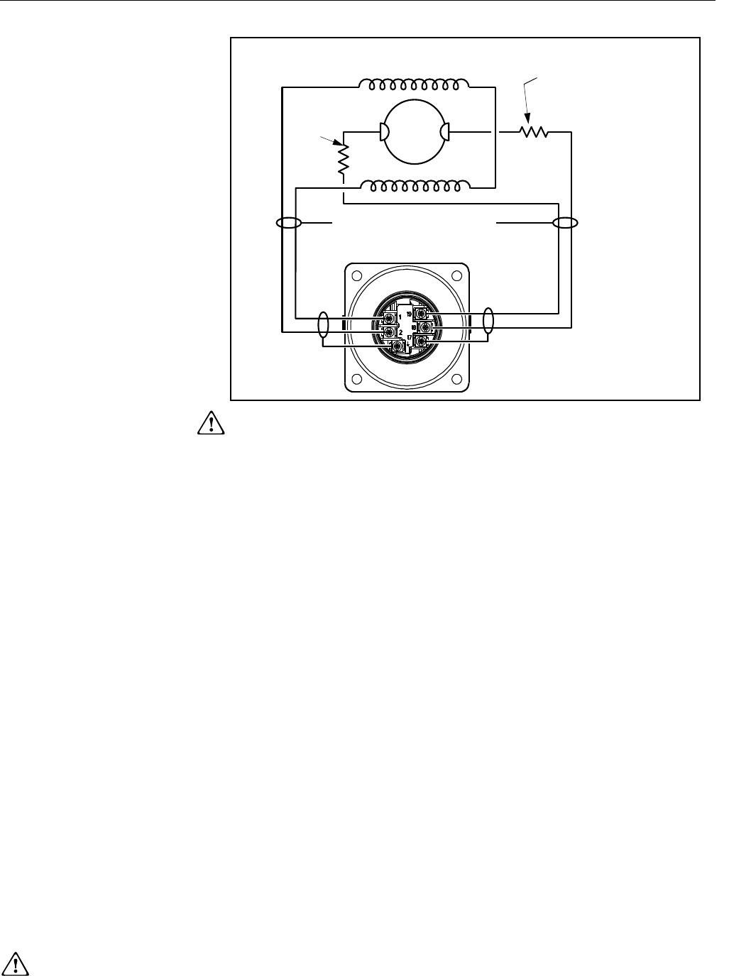
Figure 6-1. Sensor Circuit
Diagram
Step 4: Uninstalled
Sensor Tests
An uninstalled sensor can also be used for sensor troubleshooting. To
interpret the results, the hazardous location certification for the sensor must
be known. Applicable codes for the Rosemount 8705 are N0, N5, and KD.
Applicable codes for the Rosemount 8707 are N0 and N5. Applicable codes
for the Rosemount 8711 are N0, N5, E5, and KD.
A sensor circuit diagram is provided in Figure 6-1. Take measurements from
the terminal block and on the electrode head inside the sensor. The
measurement electrodes, 18 and 19, are on opposite sides in the inside
diameter. If applicable, the third grounding electrode is in between the other
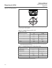
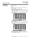
two electrodes. On Rosemount 8711 sensors, electrode 18 is near the sensor
junction box and electrode 19 is near the bottom of the sensor (Figure 6-2).
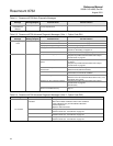
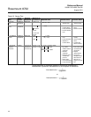
The different sensor models will have slightly different resistance readings.
Flanged sensor resistance readings are in Table 6-6 while wafer sensor
resistance readings are in Table 6-7.
68.1k⍀ (not applicable for
sensors with N0 hazardous
certification approval option
code)
Sensor Housing
68.1k⍀
See “Safety Information” on page 6-1 for complete warning information.