


Reference Manual
00809-0100-4665, Rev AA
August 2010
Rosemount 8732
2-6
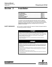
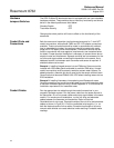
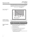
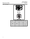
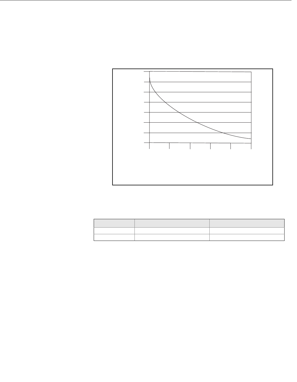
Figure 2-3 shows the supply current for each corresponding supply voltage.
For combinations not shown, you can calculate the maximum distance given
the supply current, the voltage of the source, and the minimum start-up
voltage of the transmitter, 12 V DC, using the following equation:
Figure 2-3. Supply Current
versus Input Voltage
Installation Category The installation category for the Rosemount 8732 is (overvoltage) Category II.
Overcurrent Protection The Rosemount 8732 Flowmeter Transmitter requires overcurrent protection
of the supply lines. Maximum ratings of overcurrent devices are as follows:
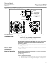
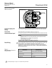
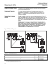
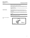
Connect Transmitter
Power
To connect power to the transmitter, complete the following steps.
1. Ensure that the power source and connecting cable meet the
requirements outlined on page 2-7.
2. Turn off the power source.
3. Open the power terminal cover.
4. Run the power cable through the conduit to the transmitter.
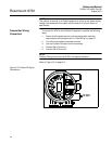
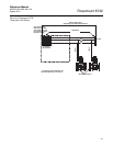
5. Connect the power cable leads as shown in Figure 2-4.
a. Connect AC Neutral or DC- to terminal 9.
b. Connect AC Line or DC+ to terminal 10.
c. Connect AC Ground or DC Ground to the ground screw mounted
inside the transmitter enclosure.
MaximumResis cetan
SupplyVoltage 12– VDC
1amp
--------------------------------------------------------------------=
Power Supply (Volts)
I = 10/V
I = Supply current requirement (Amps)
V = Power supply voltage (Volts)
Supply Current (Amps)
12 18
24
30
36
42
0.2
0.3
0.4
0.5
0.6
0.7
0.8
0.9
Power System Fuse Rating Manufacturer
95-250 Vac 250 V; 2 Amp, Quick Acting Bussman AGCI or Equivalent
42 Vdc 50 V, 3 Amp, Quick Acting Bussman AGCI or Equivalent