Reference Manual
00809-0100-4665, Rev AA
August 2010
Rosemount 8732
5-4
SENSOR MOUNTING Physical mounting of a sensor is similar to installing a typical section of pipe.
Conventional tools, equipment, and accessories (bolts, gaskets, and
grounding hardware) are required.
Upstream/Downstream
Piping
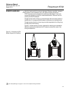
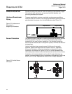
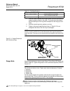
To ensure specification accuracy over widely varying process conditions,
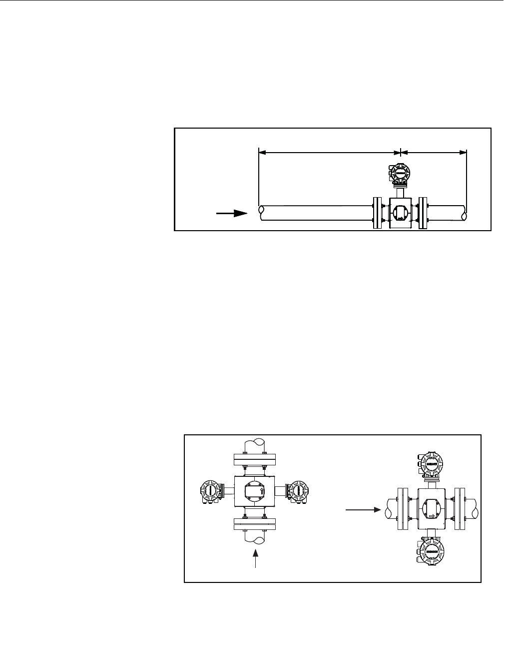
install the sensor a minimum of five straight pipe diameters upstream and two
pipe diameters downstream from the electrode plane (see Figure 5-2).
Figure 5-2. Upstream and
Downstream
Straight Pipe Diameters
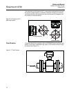
Sensor Orientation The sensor should be installed in a position that ensures the sensor remains
full during operation. Figures 5-3, 5-4, and 5-5 show the proper sensor
orientation for the most common installations. The following orientations
ensure that the electrodes are in the optimum plane to minimize the effects of
entrapped gas.
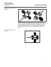
Vertical installation allows upward process fluid flow and is generally
preferred. Upward flow keeps the cross-sectional area full, regardless
of flow rate. Orientation of the electrode plane is unimportant in vertical
installations. As illustrated in Figures 5-3 and 5-4, avoid downward flows
where back pressure does not ensure that the sensor remains full at all times.
Installations with reduced straight runs from 0 to five pipe diameters are
possible. In reduced straight pipe run installations, performance will shift to as
much as 0.5% of rate. Reported flow rates will still be highly repeatable.
Figure 5-3. Vertical Sensor
Orientation
FLOW
5 Pipe Diameters
2 Pipe Diameters
FLOW
FLOW


