


Reference Manual
00809-0100-4665, Rev AA
August 2010
Rosemount 8732
2-4
Hardware
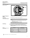
Jumpers/Switches
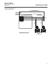
The 8732 Profibus PA electronics board is equipped with two user-selectable
hardware switches. These switches do not have any functionality and should
be left in the default positions as listed below:
Changing the switch position will have no effect on the functionality of the
electronics.
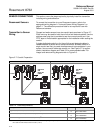
Conduit Ports and
Connections
Both the sensor and transmitter junction boxes have ports for
1
/2-inch NPT
conduit connections, with optional CM20 and PG 13.5 adapter connections
available. These connections should be made in accordance with national,
local or plant electrical codes. Unused ports should be sealed with metal
plugs and PTFE tape or other thread sealant. Connections should also be
made in accordance with area approval requirements, see examples below
for details. Proper electrical installation is necessary to prevent errors due to
electrical noise and interference. Separate conduits are not necessary for the
coil drive and signal cables connecting the transmitter to the sensor, but a
dedicated conduit line between each transmitter and sensor is required. A
shielded cable must be used.
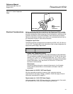
Example 1: Installing flanged sensors into an IP68 area. Sensors must be
installed with IP68 cable glands and cable to maintain IP68 rating. Unused
conduit connections must be properly sealed to prevent water ingress. For
added protection, dielectric gel can be used to pot the sensor terminal block.
Consult technical document 00840-0100-4750 when installing meters into an
IP68 installation.
Example 2: Installing flowmeters into explosion proof/flameproof areas.
Conduit connections and conduit must be rated for use in the hazardous area
to maintain flowmeter approval rating. Consult Appendix B: of this manual for
installation requirements for hazardous areas.
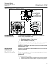
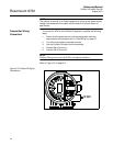
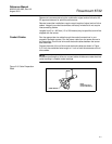
Conduit Cables Run the appropriate size cable through the conduit connections in your
magnetic flowmeter system. Run the power cable from the power source to
the transmitter. Do not run power cables and output signal cables in the same
conduit. For remote mount installations, run the coil drive and electrode
cables between the flowmeter and transmitter. Refer to Electrical
Considerations for wire type. Prepare the ends of the coil drive and electrode
cables as shown in Figure 2-2. Limit the unshielded wire length to 1-in. on
both the electrode and coil drive cables. Excessive lead length or failure to
connect cable shields can create electrical noise resulting in unstable meter
readings.
Simulate Enable OFF
Transmitter Security OFF