


Reference Manual
00809-0100-4665, Rev AA
August 2010
Rosemount 8732
6-2
INSTALLATION CHECK
AND GUIDE
Use this guide to check new installations of Rosemount magnetic flowmeter
systems that appear to malfunction.
Before You Begin
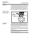
Transmitter
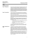
Apply power to your system before making the following transmitter checks.
1. Verify that the correct sensor calibration number is entered in the
transmitter. The calibration number is listed on the sensor nameplate.
2. Verify that the correct sensor line size is entered in the transmitter.
The line size value is listed on the sensor nameplate.
3. Verify that the function blocks are not in Out of Service mode.
4. Verify that the transmitter is functioning correctly by using the 8714i
Meter Verification diagnostic or the 8714D Calibration Reference
Standard.
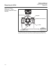
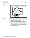
Sensor
Be sure that power to your system is removed before beginning sensor
checks.
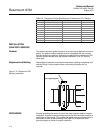
1. For horizontal flow installations, ensure that the electrodes remain
covered by process fluid.
For vertical or inclined installations, ensure that the process fluid
is flowing up into the sensor to keep the electrodes covered by
process fluid.
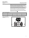
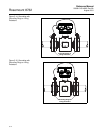
2. Ensure that the grounding straps on the sensor are connected to
grounding rings, lining protectors, or the adjacent pipe flanges.
Improper grounding will cause erratic operation of the system.
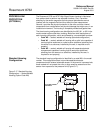
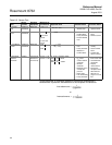
Wiring for Remote Configurations
1. The signal wire and coil drive wire must be twisted shielded cable.
Emerson Process Management, Rosemount division. recommends
20 AWG twisted shielded cable for the electrodes and 14 AWG
twisted shielded cable for the coils.
2. The cable shield must be connected at both ends of the electrode and
coil drive cables. Connection of the signal wire shield at both ends is
necessary for proper operation. It is recommended that the coil drive
wire shield also be connected at both ends for maximum flowmeter
performance
3. The signal and coil drive wires must be separate cables, unless
Emerson Process Management specified combo cable is used. See
Table 2-2 on page 2-11.
4. The single conduit that houses both the signal and coil drive cables
should not contain any other wires.
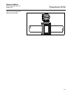
Process Fluid
1. The process fluid conductivity should be 5 microsiemens
(5 micro mhos) per centimeter minimum.
2. The process fluid must be free of air and gasses.
3. The sensor should be full of process fluid.