


58
6. Assembly
CTR6000 and CTR6500 electronics box:
Note:
These electronics boxes must not be used with
other stands. The serial number of the associated
stand has been recorded on the back of the elec-
tronics box.
A 3-axis control unit for focus and 3-plate cross
stages is integrated in the CTR6000.
A 3-axis control unit for focus and a scanning
stage is integrated in the CTR6500.
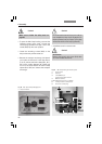
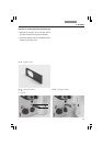
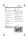
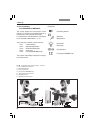
• Connect the Microscope (77.6) socket to the
back of the stand (78.5) using the 25-pin mi-
croscope cable.
• Connect the SmartMove remote control module
to the XYZ-Control socket (77.5).
• Connect the motorized stage, if present, to the
XY-Stage socket (77.2).
• Connect the lamp power cable (78.7) to the 12 V,
max 100 W socket (77.7).
Caution!
Ensure that the plugs are correctly inserted
and secured to prevent overheating of the
sockets.
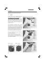
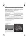
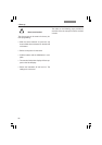
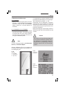
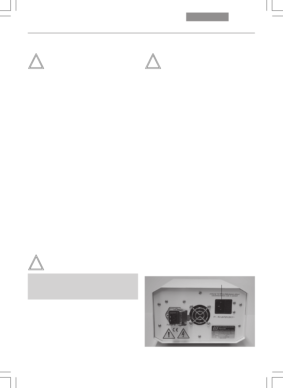
Fig. 79 Rear panel of ebq 100 supply unit
1 AC power supply socket
1
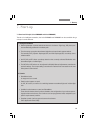
6.18 Connection to the Computer
Note:
To start the Leica Application Suite (LAS), en-
sure that the COM1 serial port is not in use by
another program or driver. This is frequently the
case when using Palms or other PDAs or when
using external modems or other devices. The
devices in question must therefore always be
disabled before using the Leica Application
Suite (LAS) software.
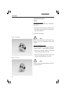
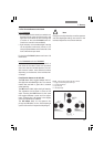
• Please use the included serial cable. Connect
the COM1 port of your PC with the RS232C
port (78.1) on the back of the stand.
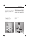
6.19 Connection to the Power Supply
• Once all installation work is complete, con-
nect the electronics box to an AC power outlet
with the included power cable (socket 77.1).
• If you are using the external ebq 100 supply
unit, connect it to an AC power outlet at this
time (socket 79.1).