


33
6. Assembly
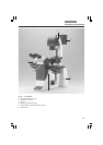
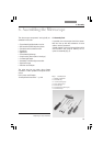
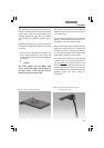
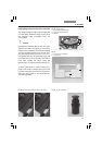
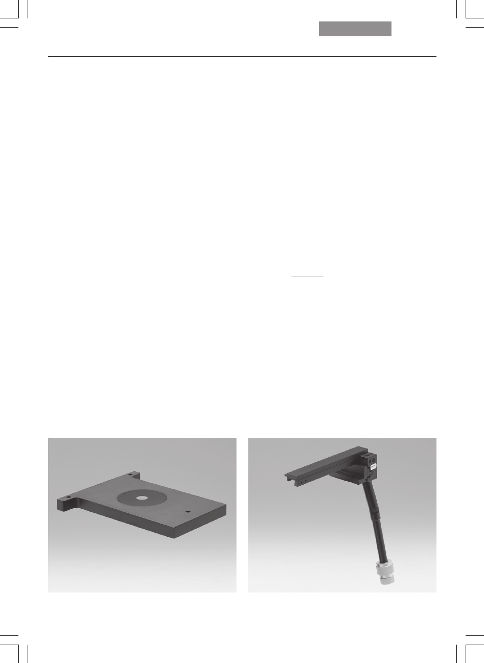
Fig. 17 Fixed micromanipulation stage
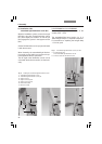
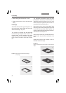
Fig. 18 Attachable mechanical stage for fixed
micromanipulation stage
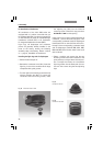
The assembly of these stages is identical. The
stages are solidly attached to the microscope by
three screws. In the case of fixed stages, an at-
tachable mechanical stage may be installed
(Fig. 18). These are supplied in a separate pack-
age.
Multiple-plate stages are supplied separately.
Like the fixed stages, these stages are mounted
as follows:
• If the screws for the stage are already in the
stand, remove them first. In most cases, the
screws will be found in the packing material
of the stand.
Caution!
The screw lengths may vary. When using
screws of different lengths, use the shorter of
the three screws in the front hole and the
equally long ones in the rear holes.
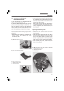
• Use a clean cloth to remove dust and packing
material residue from the stand’s contact sur-
face for the stage.
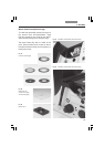
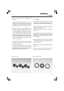
• Align the stage so that the pair of holes faces
back toward the illumination axis and the sin-
gle hole faces forward toward the tube.
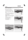
• Align the mounting holes in the stage with the
holes in the support surface. If the holes are
covered in the case of 3-plate cross-stages or
scanning stages, please shift the upper stage
plate until the opening becomes visible.
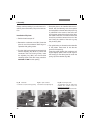
• First, tighten the single front screw with the
included 3 mm hex screwdriver. Be sure to
use the
shortest of the three screws in the
front hole, as an excessively long screw can
interfere with the focus travel. (If you have a
rotating stage, please continue reading under
“Rotating Stage and Insert Frame for
Coverslips”).
!