


38
6. Assembly
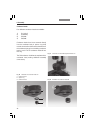
6.5 Installation of Condensers
All condensers of the Leica DMI series are
equipped with a 7-position turret disk that can
be equipped with light rings phase contrast (PH)
or dark field (DF), IC prisms for transmitted-light
interference contrast (DIC)
or slit illuminators
for integrated modulation contrast (IMC).
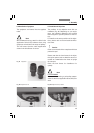
Light rings, slit diaphragms and condenser
prisms are generally already installed in the
turret at the factory, making the following
assembly steps unnecessary. Please continue
on →
page 41, Installation of Condensers.
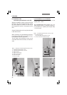
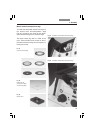
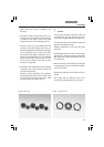
Installing the light rings and slit diaphragms
• Switch the microscope off.
• Remove the condenser cover (38.1). Insert the
light ring in one of the condenser disk’s large
receptacles with guide grooves.
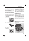
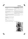
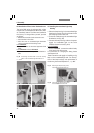
•Turn the right-hand centering screw back fully
with the adjusting key (39.2). To prevent the
condenser disk from turning further, insert
the adjusting key (39.2) into the left-hand
centering screw of the disk. It may protrude a
maximum of 1 mm into the opening.
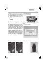
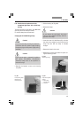
Insert light rings for Phaco (marked with the ID
numbers 0, 1, 2, 3 and the focal intercept S of the
corresponding condenser head), DF diaphragms
(marked with a D for dark field and the focal in-
tercept S of the corresponding condenser head)
and slit diaphragms (marked M05, M10, M20,
M40 and M63)
in the location holes of the turret
disk as follows:
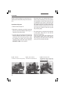
• Select a position and ensure that the two
mounting screws have been released to the
point that they no longer extend into the posi-
tion. To adjust the screws, turn the desired
light ring position into the beam path. You can
now turn the screws using the two adjusting
keys.
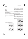
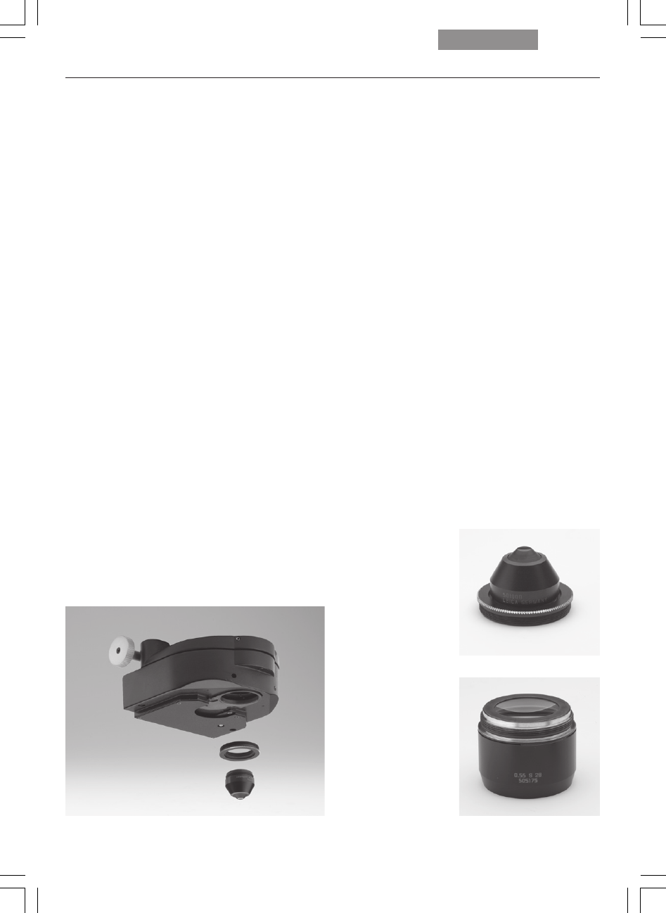
Fig. 35
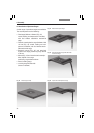
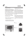
Condenser head S28
Fig. 33 Condenser base S1-S28
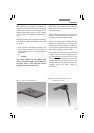
Fig. 34
Condenser head S1