


41
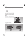
6. Assembly
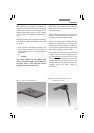
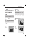
Caution:
Do not press the spring clip down under any
circumstances. This can destroy the clip or
result in an unstable position of the prism.
Turn the prism to ensure that it snaps into po-
sition and release the tool.
Remove fingerprints or dust from the prism
with care.
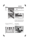
• Use the left centering screw to roughly center
the prism. The right centering screw must not
restrict the range of adjustment under any cir-
cumstances.
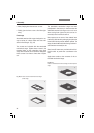
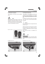
• Note the number of the opening and the prism
designation for entry into the Leica Applica-
tion Suite (LAS).
• Remove the adjusting key and close the con-
denser.
• Fine adjust with the Bertrand lens or tel-
escope after switching the unit on (Fig. 32).
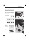
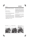
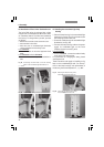
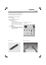
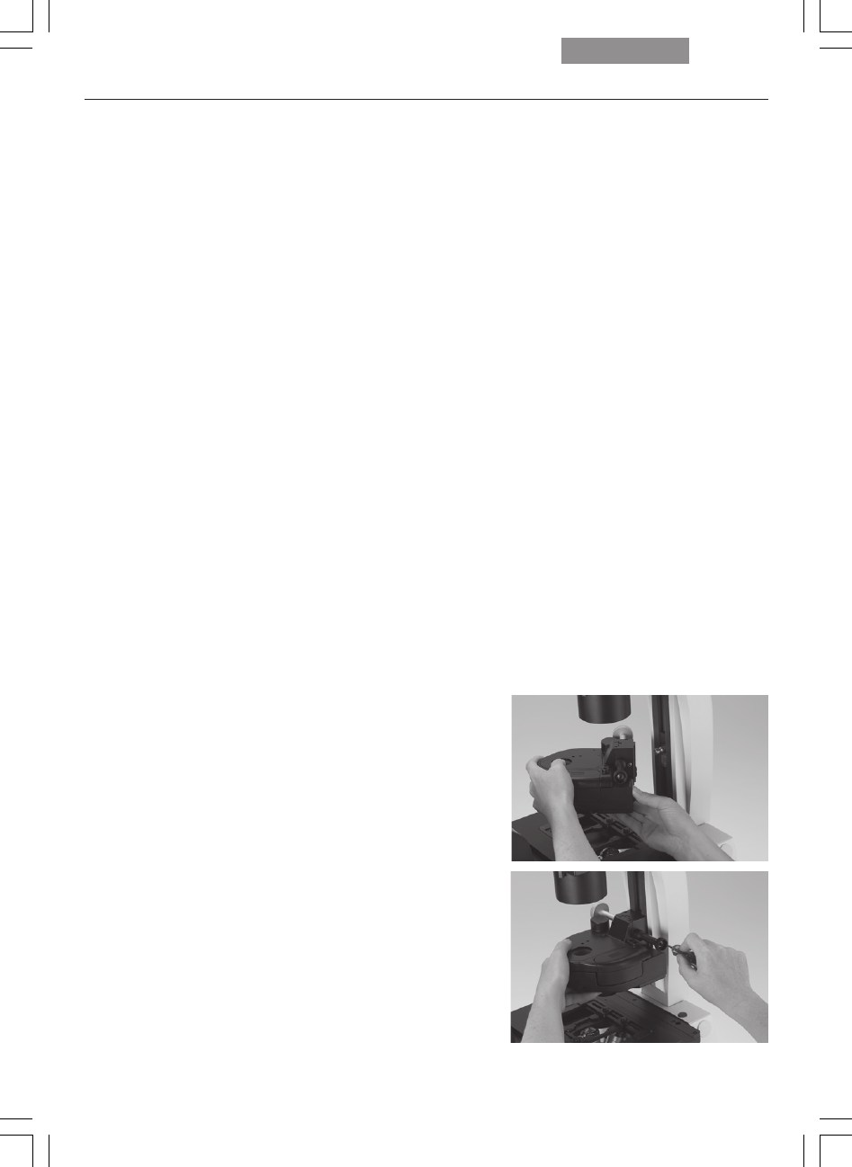
Installation of Condensers
The installation procedure is identical for all
condensers S1 to S70 (motorized or manual/
coded).
Release the socket head screw at the right side
of the condenser holder. Place the condenser on
the retaining pins of the illumination arm and
move the condenser to the correct height. Use
the markings on the column and condenser to
determine the correct position.
Once you have reached the correct position,
tighten the socket head screw.
Fig. 40 Installation of condenser on
transmitted-light illumination arm
!