


31
6. Assembly
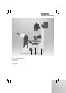
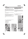
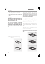
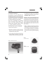
Fig. 12 IC objective prism
1 Objective prism in frame
2 Screw and washer
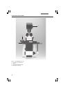
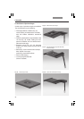
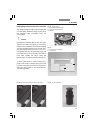
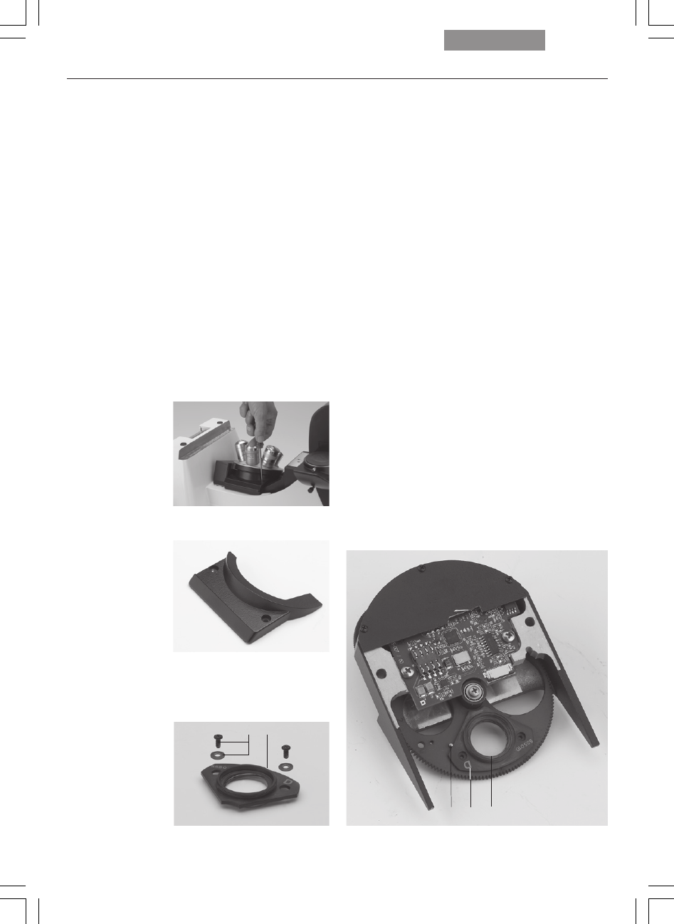
Fig. 10b DIC objective prism turret (coded and motorized)
1 IC objective prism in frame
2 Identification letter (ID)
3 Orientation pin
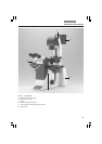
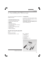
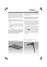
Fig. 11 Front cover, DIC prism disk
6.3 Installation of the DIC Module
and DIC Objective Prisms
If your microscope is not equipped with DIC,
please continue with Chapter 6.4.
In the Leica DMI series microscopes, the DIC
prisms are already installed in the DIC disk be-
low the objective turret (Fig. 10b).
Motorized,
manual coded and manual DIC disks are avail-
able. The installation is identical for all types.
Proceed as follows when making changes to the IC
prism disk:
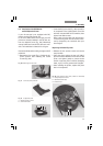
• Remove the front cover (Fig. 11) below the ob-
jective revolver after releasing the socket
screws (Fig. 10a).
• Insert the DIC prism disk (Fig. 10b) squarely in
its receptacle. First, lightly tighten one screw
with the included 3mm hex screwdriver, then
tighten both Allen screws.
Note: insert the prism disk with the electron-
ics board facing down.
Do not touch the elec-
tronics (especially the contacts) with your
bare fingers!
Replacing individual IC prisms:
• Release the two socket screws and remove
the prism disk.
• Place the prism against the stop pin (10b.3),
place the washer between the screw and the
prism, and tighten gently to prevent undue
tension. Insert the prism so that its identifying
letter, e.g. ID, is facing upward and is legible.
• After installing the prisms, replace the prism
disk in its receptacle.
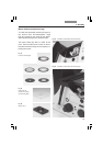
Fig. 10a Removing the front cover
321
2
1