


30
6. Assembly
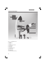
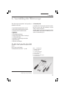
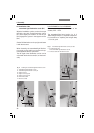
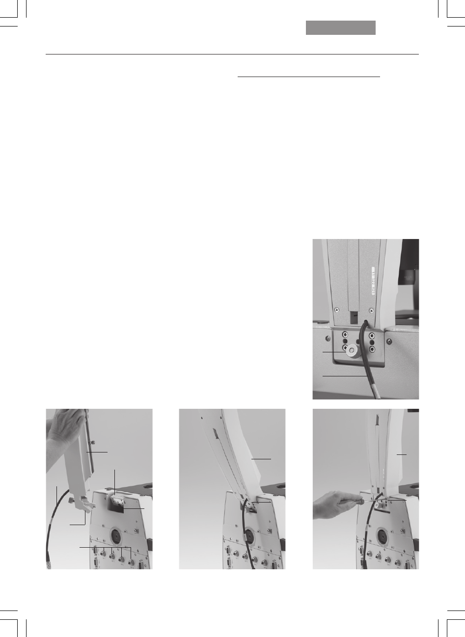
6.2 Installation of the
transmitted-light illumination carrier (DL)
Wipe the installation surface on the microscope
(8.3) with a dry cloth. Tip the illumination carrier
(8.1) back slightly and install it so that the pin
(8.2) engages the groove in the support surface
(8.4).
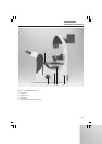
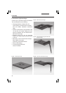
Set the DL illumination carrier upright and fasten
it with the 4 screws.
When fastening the transmitted-light illumina-
tion carrier, do not hold it so as to ensure its op-
timal alignment with the optical axis.
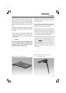
The tilt angle of the illumination carrier can be
varied with the knurled screw (9.1) or fixed verti-
cally.
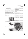
Leica DMI4000B and Leica DMI6000B
Connect the electronics cable to one of the
sockets, EXT1 - EXT4.
The transmitted-light lamp housing for 12 V
100 W halogen lamps is a separate component.
For instructions on replacing the halogen lamp
→
Ch. 6.10, p. 45.
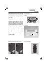
Fig. 9 Transmitted-light illumination carrier, rear side
1 Knurled locking knob
of the transmitted-light illumination carrier
2 Connector cable for the electronics box
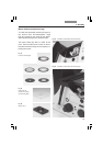
Fig. 8 Installing the transmitted-light illumination carrier
1 Transmitted-light illumination carrier
2 Transmitted-light illumination carrier pin
3 Support surface
4 Support surface groove
5 Support surface groove
6 EXT1-EXT4 sockets
7 Electronics cable
1
2
1
3
4
7
2
6
1
5
1
5