


57
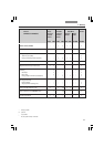
6. Assembly
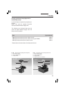
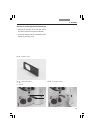
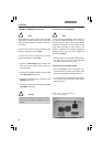
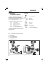
Fig. 78 Rear view of stand
1 RS232 ports
2 2 x USB
3 4 x EXT.
4 XYZ control for SmartMove
5 Electronic box connection
6 Condenser cable
7 Lamp power cable
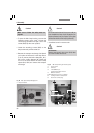
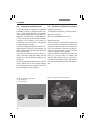
Fig. 77 Rear view of CTR6000
1 AC power socket
2 XY Stage socket for motorized stage
3 Direct interface socket optional
4Z Control for separate focus control
5 XYZ Control for SmartMove
6 Microscope socket for microscope
7
12 V, max 100 W for the lamp power cable of stand
8 DL: reset button
7
1
2
3
4
5
8
6
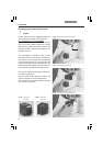
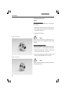
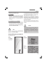
6.17 Connection to the Electronics Box
CTR4000, CTR6000 or CTR6500
The Leica DMI 3000 B is supplied without an
electronics box. The power supply is integrated
in the stand and a socket has been provided on
the back of the microscope to connect the
transmitted-light illumination. The illuminated
ON/OFF switch is located on the stand.
CTR 4000 electronics box
The Leica DMI 4000 B is supplied with the
CTR4000 electronics box. The power supply for
the microscope is located in this box. Two sock-
ets are located on the back of the CTR4000 elec-
tronics box for 12V/100W transmitted-light and
12V/100W incident-light illuminators. The illumi-
nated ON/OFF switch for the microscope is lo-
cated on the CTR4000 electronics box.
1
2
3
7
6
5
4