


39
6. Assembly
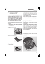
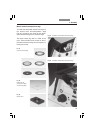
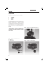
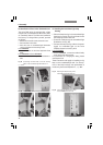
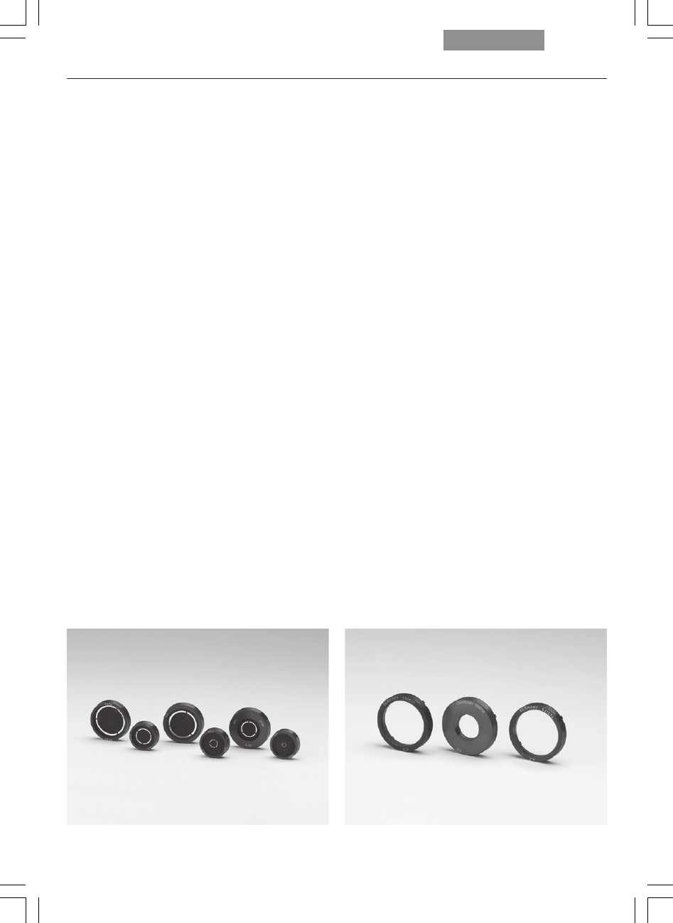
• Next, take the special condenser tool
(Fig. 39.1).
• If possible, install the light rings 0 to 3 in as-
cending order. The numbering of the openings
is located at the edge of the crown gear
(4 large openings: 1-4; 3 small openings: 5-7).
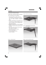
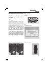
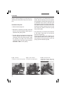
• Grasp the light ring to be installed with the
condenser tool (the lettering must face up-
ward and be legible) so that the tab of the light
ring is positioned to the center of the tool’s
cam and the upper edge of the light ring is ly-
ing flat in the holder of the tool. The numbers
should be positioned toward the end of the
tool. Press the cheeks of the tool to grasp
the light ring (Fig. 39a).
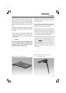
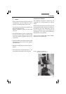
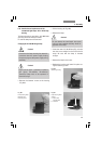
•Two guide hooks are located on the underside
of the light rings. These must fit into the two
grooves of the opening.
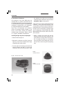
Insert the light ring (holding the condenser
tool angled slightly upward and at a 90° angle
to the housing) so that the mount fits under
the spring clip of the retainer (Fig. 3).
Caution:
Do not press the spring clip down under any
circumstances. This can destroy the clip or
result in an unstable position of the light ring.
Turn the light ring to ensure that it snaps into
position and release the tool.
Remove fingerprints or dust from the prism
with care.
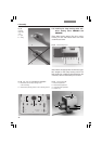
• Use the left centering screw to roughly center
the light ring. The right centering screw must
not restrict the range of adjustment under any
circumstances.
• Note the number of the opening and the light
ring designation for entry into the Leica Appli-
cation Suite (LAS).
• Remove the adjusting key and close the con-
denser.
• Fine adjust with the Bertrand lens or tel-
escope after switching the unit on (Fig. 32).
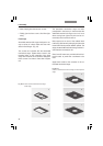
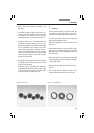
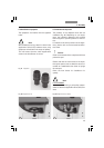
Fig. 36 Phase rings Fig. 37 Condenser prisms
!