


40
6. Assembly
Please continue reading if you also have to in-
stall IC prisms. Otherwise, skip to the next sec-
tion.
Installation of IC prisms
• Switch the microscope off.
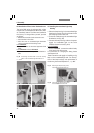
• Remove the condenser cover (38.1). Insert the
prism in one of the condenser disk’s large re-
ceptacles with guide grooves.
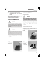
•Turn the right-hand centering screw back fully
with the adjusting key (39.2). To prevent the
condenser disk from turning further, insert
the adjusting key (39.2) into the left-hand
centering screw of the disk. It may protrude a
maximum of 1 mm into the opening.
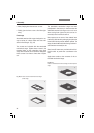
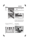
• Grasp the prism to be installed with the con-
denser tool (the lettering must face upward
and be legible) so that the tab of the prism ring
is positioned to the center of the tool’s cam
and the upper edge of the prism is lying flat in
the holder of the tool. The numbers K2 to K16
should be positioned toward the end of the
tool. Press the cheeks of the tool to grasp
the prism (Fig. 39a).
•Two guide hooks are located on the underside
of the prisms. These must fit into the two
grooves of the opening.
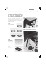
Insert the prism (holding the condenser tool
angled slightly upward and at a 90° angle to
the housing) so that the mount fits under the
spring clip of the retainer (Fig. 39a).
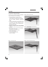
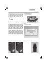
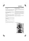
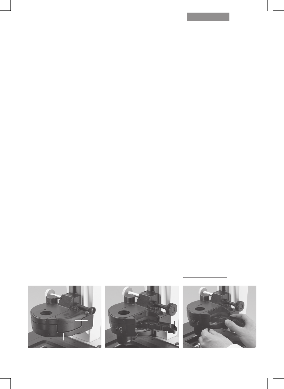
Fig. 38 Condenser
1 condenser cover, 2 centering opening
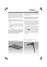
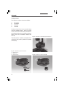
Fig. 39 Open condenser
1 condenser tool, 2 adjusting key
1
1
2
1
2
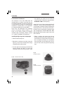
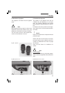
Fig. 39a Inserting the prism
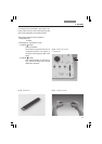
The designation must be visible when
installed and oriented toward the
center of the condenser.
DIC images are not possible otherwise.