


45
4. Insert the two (2) new and two (2) existing hex
screws through the wheelchair frame, axle
mounting bracket and cross member assembly
and securely tighten with locknuts.
5. Install the hooked end of the ventilator tray over
the front lower cross member and loosely tighten
with two (2) button screws and locknuts.
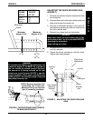
6. Center the ventilator tray on the rear cross mem-
ber by making sure the ventilator tray is in the
same hole on the right and left sides of the cross
member assembly. See chart in FIGURE 1.
7. Insert two (2) button screws through the coved
washers, and cross member assembly and se-
curely tighten.
8. Securely tighten the front two (2) button screws.
WARNING
Anti-tippers MUST be fully engaged and spring
buttons fully protruding out of adjustment
holes.
9. Press the release buttons IN and insert the anti-
tippers into the cross member assembly until the
buttons lock in place.
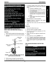
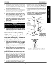
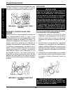
INSTALLING THE I.V. POLE (FIGURE 2)
NOTE: The A-T wheelchair must use 12-inch rear
wheels when using the I.V. pole option.
NOTE: Before installing the I.V. pole onto the
wheelchair, determine if it will be mounted on
the right or left side of the wheelchair.
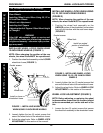
1. Install the mounting bracket onto the I.V. pole
making sure the mounting bracket wraps BE-
HIND the back cane as shown in FIGURE 2 by
sliding the mounting bracket onto the bottom of
the I.V. pole.
2. Remove the existing rear hex screw and lock-
nut that secure the seat adjustment plate to the
seat frame.
NOTE: Keep existing hex screw for future use.
3. Install the new hex screw through the new
washer, I.V. pole, new spacer, I.V. pole, new
washer, seat adjustment plate, coved washer,
seat frame, coved washer, seat adjustment plate,
new washer and loosely tighten with existing
locknut.
4. Line up the mounting bracket on the I.V. pole
with the top mounting hole in the back cane.
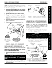
5. Install the button screw through the mounting
bracket and back cane from the INSIDE of the
back cane and securely tighten with the locknut.
6. Securely tighten the lower hex screw and lock-
nut that secures the I.V. pole to the wheelchair
frame.
7. Adjust the height of the I.V. pole by turning the
adjustment lock COUNTERCLOCKWISE to
loosen and CLOCKWISE to tighten.
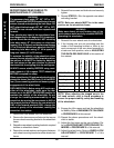
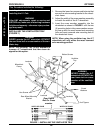
FIGURE 2 - INSTALLING THE I.V. POLE
Button Screw
Locknut
Washer
RIGHT
MOUNTING
BRACKET
POSITION
Adjustment
Lock
I.V. Pole
Washer
Locknut
Spacer
Washer
Coved Washers
(Between Seat
Adjustment Plate
and Seat Frame)
LEFT MOUNTING
BRACKET
POSITION
Hex
Screw
O
P
T
I
O
N
S
PROCEDURE 8OPTIONS