


14
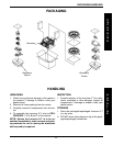
This Procedure includes the following:
60
o
, 70
o
and 90
o
Swingaway Footrest Installation
60
o
, 70
o
and 90
o
Swingaway Footrest Height
Adjustment
Assembly of the 90
o
Footrest Extension
Installing Adjustable Angle Flip-up Footplate Hinge
Installing/Adjusting Adjustable Angle Flip-up
Footplates
Impact Guards/Calf Strap/H-Strap
Composite/Articulating Footplate Heel Loop
Replacement
Elevating Legrest /Calfpad Assembly
Adjusting the Elevating Legrest Calfpad Assembly
Adjusting Contracture Platform and Bilateral Con-
tracture Platform - Height, Angle and Depth
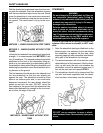
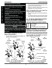
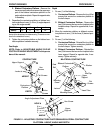
FRONT RIGGINGSPROCEDURE 1
Mounting tube
70
o
Footrest
90
o
Footrest
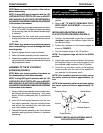
FIGURE 1 - 60
O
, 70
O
AND 90
O
SWINGAWAY
FOOTREST INSTALLATION
2. Insert the footrest mounting pin into the mount-
ing tube of the wheelchair frame.
3. Rotate the footrest towards the inside of the
wheelchair until it locks into place.
NOTE: The footplate will be on the inside of the
wheelchair when locked in place.
4. Repeat this procedure for the other footrest as-
sembly.
5. To release the footrest, push the footrest release
lever inward while rotating the footrest outward.
60
o
, 70
o
AND 90
o
SWINGAWAY FOOTREST
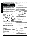
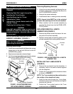
HEIGHT ADJUSTMENT (FIGURE 2)
FOOTREST HEIGHT ADJUSTMENT RANGES:
60
o
13-17-inches
70
o
13-17-inches
90
o
5-8-inches
✪ 90
o
5-11-inches (with 3-inch extension)
✪✪
✪✪
✪ Refer to ASSEMBLY of 90
o
FOOTREST EX-
TENSION in this section, then perform FOOT-
REST HEIGHT ADJUSTMENT PROCEDURE.
NOTE: Release the footrest locking mechanism
and lift the footrest mounting pins out of their
mounting tubes. Lay the assembly on a flat sur-
face to simplify this procedure.
Hex screw
Locknut
70
o
Footrest
Height adjustment
holes
60
o
Footrest
Hex screw
Coved
Washer
FIGURE 2 - 60
o
, 70
o
and 90
o
SWINGAWAY
FOOTREST HEIGHT ADJUSTMENT
90
o
Footrest
3-inch extension
Hex screw
WARNING
After ANY adjustments, repair or service and BE-
FORE use, make sure all attaching hardware is
tightened securely - otherwise injury or damage
may result.
60
o
, 70
o
and 90
o
SWINGAWAY FOOTREST
INSTALLATION (FIGURE 1)
1. Turn the footrest to the side (open footplate is per-
pendicular to the wheelchair).
Footrest
release lever
Footrest
mounting pin
Footrest
release
lever
60
o
Footrest
Footrest
release
lever
Footrest
mounting
pin
Height adjustment holes
F
R
O
N
T
R
I
G
G
I
N
G
S