


35
TILT-IN-SPACE PROCEDURE 5
T
I
L
T
I
I
N
S
P
A
C
E
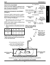
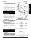
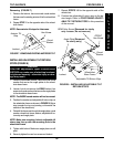
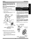
Removing (FIGURE 7)
1. Remove the locknut, hex screw and coved washer
that secures the existing anterior tilt to the wheelchair
frame.
2. Repeat STEP 1 for the opposite side of the wheel-
chair frame.
NOTE: Save anterior tilt stops for future use.
FIGURE 7 - REMOVING EXISTING ANTERIOR TILT
Coved
Washer
Locknut
Hex Screw
Anterior Tilt
Stop
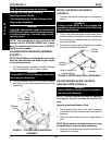
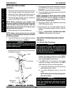
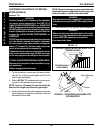
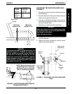
INSTALLING ADJUSTABLE TILT RETURN
STOPS (FIGURE 8)
WARNING
After ANY adjustments, repair or service and
BEFORE use, make sure all attaching hardware
is tightened securely - otherwise injury or dam-
age may result.
1. Remove the FRONT locknut, hex screw and coved
washer that secure the angle plates to the wheel-
chair base frame.
2. Loosen, but do not remove the REAR locknut, hex
screw and coved washers that secure the angle plates
to the wheelchair base frame.
NOTE: The INSIDE coved washer will not be reused.
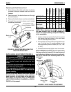
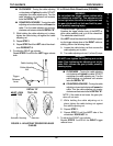
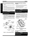
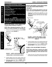
3. Position the washer and adjustable tilt return stop on
the wheelchair frame as shown in FIGURE 9 (Nylon
stop towards the top and pointing out towards the
outside of the wheelchair).
4. Reinstall the hex screw through the angle plate, coved
washer, wheelchair frame, washer, adjustable tilt re-
turn stop and angle plate.
NOTE: Make sure mounting holes in adjustable tilt
return stop line up with the mounting hole in the
wheelchair frame.
5. Tighten with locknut. Make sure angle plate can still
pivot.
6. Securely tighten the rear hex screw and locknut.
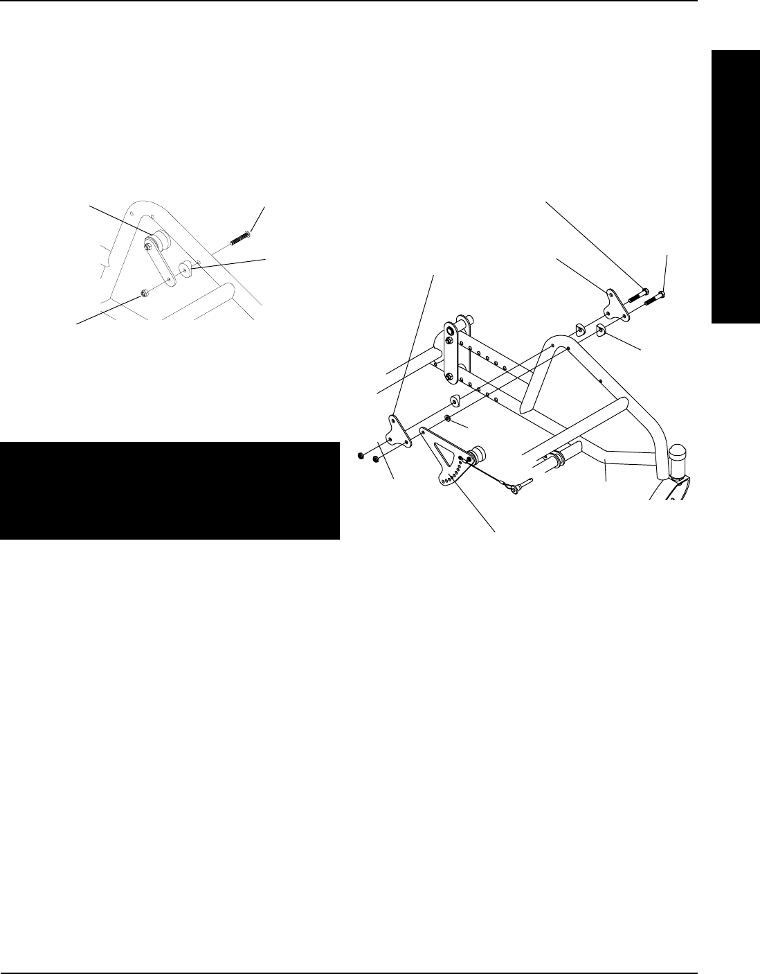
FIGURE 8 - INSTALLING ADJUSTABLE TILT
RETURN STOPS
Angle Plate
(Removed
for clarity only.)
REAR Hex Screw
(Removed for clarity
only. Loosen, Do not remove.)
FRONT
Hex Screw
Coved
Washer
Adjustable Tilt Return Stop
Wheelchair
Base Frame
Washer
Locknut
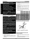
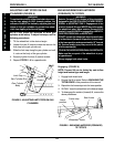
7. Repeat STEPS 1-6 for the opposite side of the
wheelchair.
8. Position the adjustable tilt return stop to the de-
sired angle. Refer to POSITIONING ADJUST-
ABLE TILT RETURN STOPS in this procedure
of the manual.