19
F
R
O
N
T
R
I
G
G
I
N
G
S
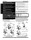
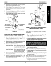
PROCEDURE 1FRONT RIGGINGS
Hex Screw
Upper
Support
Locknuts
Angle Adjustment Plate
HOLE #
4
3
2
1
ANGLE
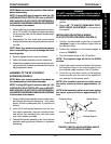
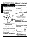
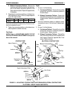
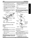
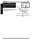
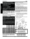
FIGURE 11 - ADJUSTING CONTRACTURE PLATFORM AND BILATERAL CONTRACTURE
PLATFORM - HEIGHT, ANGLE AND DEPTH
B. Bilateral Contracture Platform - Remove the
hex screw and locknut that secure the upper sup-
port of the bilateral contracture platform to the
angle adjustment plate. Repeat for opposite side,
if necessary.
2. Reposition the contracture platform or bilateral con-
tracture platform to one (1) of four (4) angles depend-
ing on the angle needed:
✪ ✪
✪ ✪
✪ HOLE # 1234
ANGLE 60
o
75
o
90
o
118
o
✪ Holes Numbered from the bottom of the wheelchair towards
the top of the wheelchair for reference only. (There are no num-
bers on the wheelchair frame.)
3. Tighten the contracture platform or the bilateral con-
tracture platform hardware securely.
Foot Angle
NOTE: Refer to ADJUSTABLE ANGLE FLIP-UP
FOOTPLATE ANGLE ADJUSTMENT in this proce-
dure of the manual.
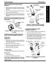
Depth
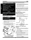
1. Do one (1) of the following:
A. Contracture Platform - Remove the four (4) flat
screws that secure the contracture platform to
the half clamps.
B. Bilateral Contracture Platform - Remove the
two (2) flat screws that secure the footplate to the
footplate clamp. Repeat for opposite side, if nec-
essary.
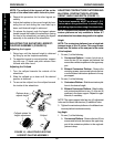
2. Move the contracture platform or bilateral contrac-
ture platform to one (1) of the three (3) desired posi-
tions.
3. Do one (1) of the following:
A. Contracture Platform - Reinstall the four (4) flat
screws that secure the contracture platform to
the half clamps. Tighten securely.
B. Bilateral Contracture Platform - Reinstall the
two (2) flat screws that secure the footplate to the
lower support. Repeat for opposite side, if nec-
essary. Tighten securely.
Hex
Screws
Locknuts
Flat Screws
Contracture
Platform
Upper Support
Button
Screws
DEPTH
HEIGHT
Spacers
Seat
Rail
Mounting
Screw
Locknut
Bilateral Contracture
Platform
Mounting Screw
Washer
End Cap
Upper
Support
CONTRACTURE
BILATERAL CONTRACTURE
Insert Tube
Flat
Screws


