36
TILT-IN-SPACEPROCEDURE 5
T
I
L
T
I
I
N
S
P
A
C
E
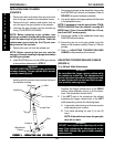
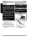
POSITIONING ADJUSTABLE TILT RETURN
STOPS (FIGURE 9)
Anterior Tilt:
WARNING
Anterior (forward) tilt is a feature of the adjustable
tilt return stops designed for the USE OF A
HEALTHCARE PROFESSIONAL or ASSISTANT
ONLY. Engagement of the anterior (forward) tilt must
NEVER be performed by the wheelchair user. When
anterior (forward) tilt is needed, it must ALWAYS be
engaged by a HEALTHCARE PROFESSIONAL or
ASSISTANT.
DO NOT operate the wheelchair when the seat frame
is in the anterior (forward) tilt position (adjustable
tilt return stops in the lower position and approxi-
mately 10
o
forward tilt). Serious bodily injury may
occur to the patient and the assistant(s).
Adjustable tilt return stops are meant to be used as
stop for the desired seat angle. NEVER use stops
as the only support for the weight of the occupant.
TO HEALTHCARE PROFESSIONALS/ASSISTANTS:
Make sure the occupant of the wheelchair is prop-
erly positioned.
Always engage both wheel locks.
1. Tilt the wheelchair to maximum tilt-in-space obtain-
able (45
o
for 15-20-inch seat depths and 35
o
for 20
and 21-inch seat depths).
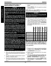
2. Refer to DETAIL "A" to determine the correct mount-
ing hole for the desired anterior tilt angle.
NOTE: Anterior (Forward) tilt can be limited by
seat-to-floor height and footrest type/length.
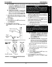
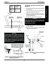
3. Push in the button on the quick-release pin and insert
quick-release pin through the wheelchair frame and
adjustable tilt return stop.
NOTE: The quick-release pin can be inserted into the
wheelchair frame and adjustable tilt return stop from
either the inside or outside of the wheelchair.
WARNING
Both adjustable tilt return stops MUST be positioned
in the same mounting hole BEFORE using the wheel-
chair.
4. Repeat STEP 2 for the opposite side of wheelchair.
WARNING
Make sure the button and detent balls of the quick-
release pin of the adjustable tilt return stop are fully
released BEFORE operating the wheelchair.
Keep detent balls clean.
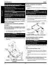
FIGURE 9 - POSITIONING ADJUSTABLE TILT
RETURN STOPS
Button
Quick-Release
Pin
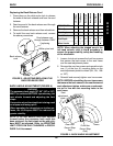
DETAIL "A"
CORRESPONDING MOUNTING HOLE FOR
DESIRED ANGLE
DESIRED ANGLE
(IN DEGREES)
30 25 20 15 10 5 0 -5 -10


