


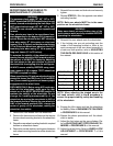

44
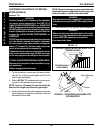
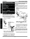
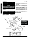
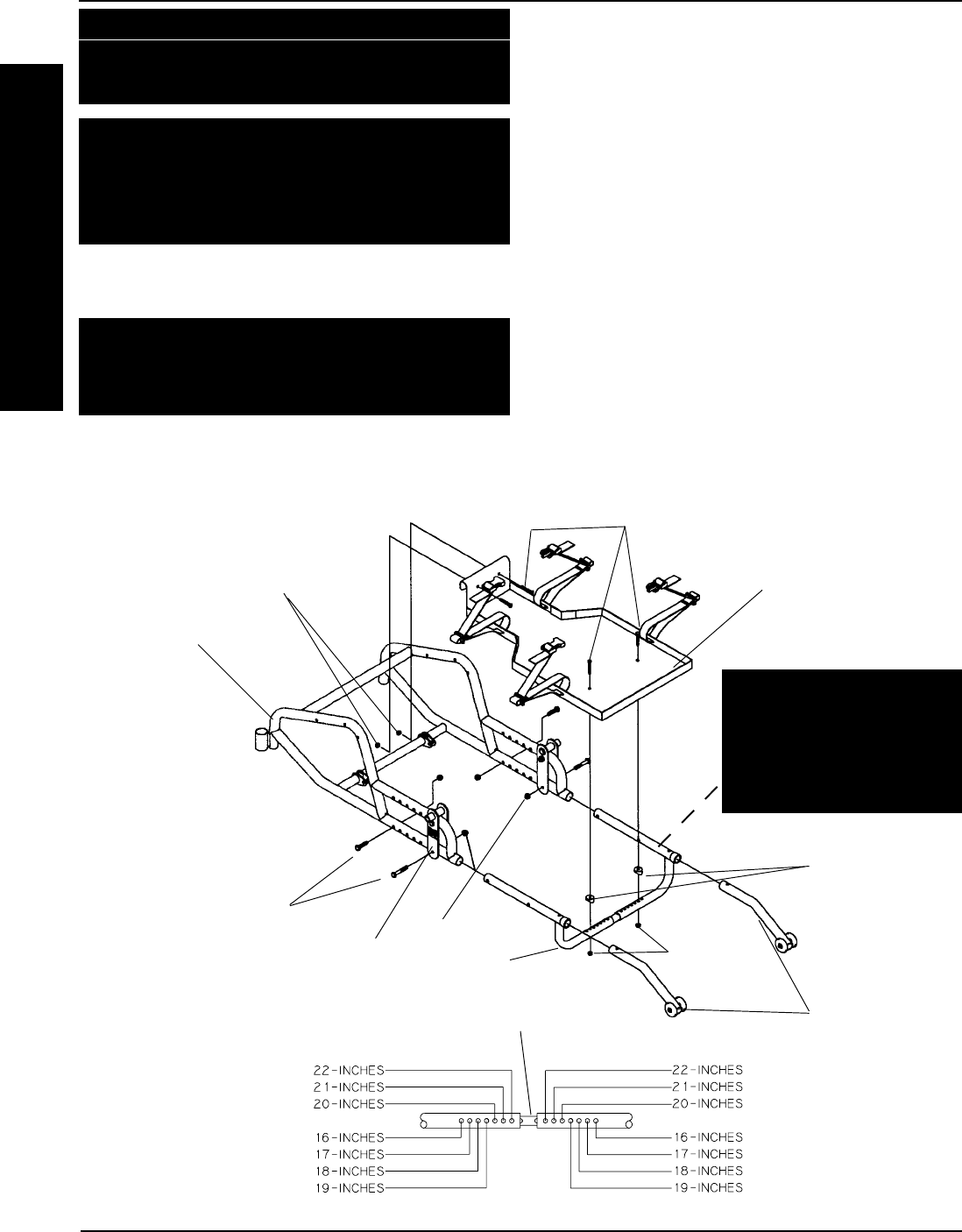
FIGURE 1 - INSTALLING THE VENTILATOR TRAY
Ventilator
Tray
Locknuts
Locknuts
Anti-Tippers
WIDTH OF CHAIR
WIDTH OF CHAIR
Coved
Washers
WARNING
NEVER operate the A-T
wheelchair WITHOUT the
rear frame bolt on cross
member of the ventilator
tray.
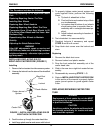
Rear Frame
Bolt On Cross
member
This Procedure includes the following:
Installing the Ventilator Tray
Installing the I.V. Pole
WARNING
After ANY adjustments, repair or service and
BEFORE use, make sure all attaching hardware
is tightened securely - otherwise injury or dam-
age may result.
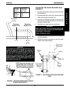
1. Remove the lower hex screws and locknuts that
secure the axle mounting bracket to the wheel-
chair frame.
2. Adjust the width of the cross member assembly
to match the width of the A-T wheelchair.
3. Insert the cross member assembly into the
wheelchair as shown in FIGURE 1 until the two
(2) mounting holes in the cross member assem-
bly line up with the most forward axle mounting
hole and most rearward axle mounting hole in
the wheelchair frame.
NOTE: When using the ventilator tray, the A-T
wheelchair will only utilize the most rearward
axle mounting position.
Button Screws
Hex Screws
INSTALLING THE VENTILATOR TRAY
(FIGURE 1)
WARNING
NEVER operate the A-T wheelchair WITHOUT
the rear frame bolt on cross member of the ven-
tilator tray.
NOTE: The Ventilator Tray is only available to
Invacare A-T wheelchairs that have been de-
signed for this option.
Wheelchair
Frame
Locknuts
Rear Wheel Mounting
Bracket
OPTIONSPROCEDURE 8
O
P
T
I
O
N
S