


29
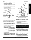
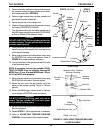
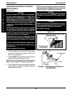
BACK ANGLE ADJUSTMENT (FIGURE 4)
WARNING
The necessary back angle (90
o
, 99
o
, 108
o
or 120
o
)
MUST be selected BEFORE repositioning the
rear wheels forward and adjusting the limit
stops.
Use caution when the wheelchair is being used
on slopes and facing uphill.
When operating the wheelchair on incline sur-
faces, the tilt-in-space MUST be reduced for
greater stability.
NOTE: IF the rear wheels have been adjusted
forward before the necessary back angle has
been achieved, the limit stops on the gas cylin-
ders MUST be adjusted. Refer to ADJUSTING
LIMIT STOPS ON GAS CYLINDERS in PROCE-
DURE 5 of this manual.
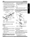
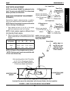
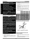
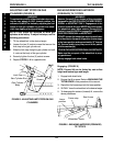
Replacing the Back Release Cord
1. Press down on the white nylon lock to release
the ends of the back release cord from the cord
fastener.
2. Feed one end of the back release cord through
the cord fastener.
3. Remove the back release cord from wheelchair.
4. To install the new back release cord, reverse
the above procedures.
FIGURE 3 - ADJUSTING/REPLACING THE
BACK RELEASE CORD
1. Loosen, but do not remove the front hex screws
that secure the back canes to the seat frame
and the seat adjustment plates.
2. Remove the rear hex screws and reposition into
one (1) of the four (4) mounting holes on the
seat adjustment plates to obtain (90
o
, 99
o
, 108
o
or 120
o
).
3. Reinstall and securely tighten rear hex screws.
NOTE: BEFORE reinstalling the rear hex screws
that secure the back canes to the seat frame and
seat adjustment plates, make sure coved wash-
ers are in line with the mounting holes in the
seat frame.
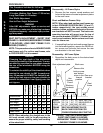
PROCEDURE: 545637
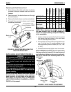
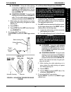
Tilt-in-Space ✓ ● ✓✓N/A ✓
Back Angle ✓✓● ✓ N/A ✓
Rear Wheels ✓✓✓● N/A ✓
Seat Depth ✓✓N/A ✓ ● ✓
Wheel Locks N/A ✓✓✓✓●
NOTE: When adjusting the shaded area in the
left hand column, refer to the
✓✓
✓✓
✓ procedure to
ensure the proper stability, safety and handling
of the wheelchair.
Limit Stops
Tilt-in-Space
Back Angle
Rear Wheels
Seat Depth
Wheel Locks
Back release
cord
BACK PROCEDURE 4
White nylon lock
Feed release cord
through fastener ONLY
if replacing
FIGURE 4 - BACK ANGLE ADJUSTMENT
Seat
frame
Front Hex
Screw (Step
One)
Rear Hex
Screw (Step
Two)
Seat
adjustment
plate
B
A
C
K