


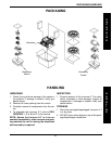

15
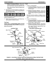
PROCEDURE 1FRONT RIGGINGS
WARNING
DO NOT overtighten. Footrest must be able to
rotate upward from horizontal to vertical position.
4. Repeat this procedure for the other footrest ex-
tension.
5. Refer to 60
o
, 70
o
AND 90
o
SWINGAWAY FOOT-
REST HEIGHT ADJUSTMENT in this section of
the manual.
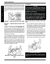
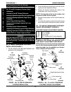
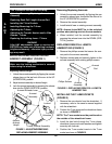
INSTALLING ADJUSTABLE ANGLE
FLIP-UP FOOTPLATE HINGE (FIGURE 3)
1. Position the adjustable angle flip-up footplate
(footplate) hinge on the footrest support tube at
the desired height.
2. Position the hardware on the footrest support as
shown in FIGURE 3.
3. Flip the footplate hinge to the UP position.
NOTE: The footplate hinge will fall to the DOWN
position.
4. Tighten the socket screw and locknut that secure
the footplate hinge to the footrest support until
the footplate hinge remains in the UP position.
5. Check the up and down motion of the footplate
hinge to make sure the user of the wheelchair
can operate the footplates easily.
NOTE: If the footplate's motion is too tight, loosen
the socket screw and locknut approximately 1/4-
turn.
NOTE: If the footplate's motion is too loose, tighten
the socket screw and locknut approximately 1/4-
turn.
NOTE: Make sure to note the position of the washers
before disassembly.
NOTE: If using ANY type of extension with the AD-
JUSTABLE FLIP-UP FOOTPLATE, refer to ADJUST-
ABLE ANGLE FLIP-UP FOOTPLATE PERPENDICU-
LAR AND/OR INVERSION/EVERSION ADJUSTMENT
in this section of the manual.
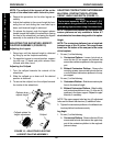
1. Remove the hex screw and coved washer (and lock-
nut on 70
o
and 90
o
) and slide the footrest up or down
on its mounting tube until the desired footrest height
is achieved.
2. Reassemble the hex screw and coved washer
through the footrest mounting hole and frame mount-
ing tube.
NOTE: Make sure washers are positioned properly
when reassembling so as not to damage the frame
mounting tubes.
3. Securely tighten the hex screw and locknut.
4. Install the footrest assembly onto the wheelchair.
5. Repeat this procedure for the opposite footrest mak-
ing sure that both footrests are mounted in the same
height adjustment holes.
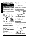
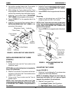
ASSEMBLY OF THE 90
o
FOOTREST
EXTENSION (FIGURE 2)
NOTE: Make sure to note position of hardware be-
fore disassembly of the footrest assembly.
NOTE: If using ANY type of extension with the AD-
JUSTABLE FLIP-UP FOOTPLATE, refer to ADJUST-
ABLE ANGLE FLIP-UP FOOTPLATE PERPENDICU-
LAR AND/OR INVERSION/EVERSION ADJUSTMENT
in this section of the manual.
1. Remove the footrest assembly from the footrest sup-
port tube by removing the hex screw, 1-inch coved
spacer, 3/4-inch coved spacer (Qty. 2), washer and
locknut.
2. Insert the 3-inch footrest extension into the foot-
rest support assembly; align the mounting holes
and secure (top mounting hole) with hex screw
and coved washer provided.
3. Reinstall the footrest assembly to the 3-inch footrest
extension paying particular attention to hardware
positioning.
F
R
O
N
T
R
I
G
G
I
N
G
S
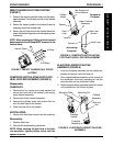
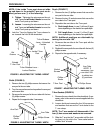
FIGURE 3 - INSTALLING ADJUSTABLE ANGLE
FLIP-UP FOOTPLATE HINGE
Footplate Hinge
Footrest Support
Washers
Coved Washer
Locknut
Socket Screw