


18
F
R
O
N
T
R
I
G
G
I
N
G
S
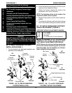
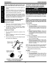
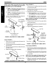
PROCEDURE 1 FRONT RIGGINGS
NOTE: The calfpad of the legrest will be on the
inside of the wheelchair when locked in place.
4. Repeat this procedure for the other legrest as-
sembly.
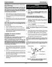
5. Adjust the footplate to the correct height by loos-
ening the nut and sliding the inner tube up or
down until desired height is achieved.
6. To release the legrest, push the legrest release
handle toward the inside of the wheelchair (facing
the front of the wheelchair) and swing the legrest
assembly to the outside of the wheelchair.
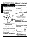
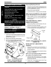
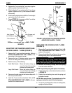
ADJUSTING THE ELEVATING LEGREST/
CALFPAD ASSEMBLY (FIGURE 10)
Adjusting the Legrest
1. Raise legs until the desired height is obtained
by lifting up on the footplate assembly.
2. To reposition legrest to normal position, support
leg with one (1) hand and push release lever
forward with other hand.
Adjusting the Calfpad
1. Turn the calfpad towards the outside of the
wheelchair.
2. Slide the calfpad up or down until the desired
position is obtained.
3. To secure the calfpad, turn the calfpad towards
the inside of the wheelchair.
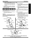
FIGURE 10 - ADJUSTING ELEVATING
LEGREST/CALFPAD ASSEMBLY
Release lever
adjusts height
Calfpad rotated for
height adjustment
Calfpad
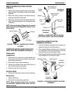
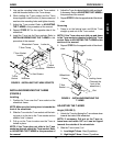
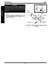
ADJUSTING CONTRACTURE PLATFORM AND
BILATERAL CONTRACTURE PLATFORM-
HEIGHT, ANGLE AND DEPTH (FIGURE 11)
WARNING
The footrest assembly MUST be at least 1-3/4-
inches above the ground/floor to avoid hitting
protruding objects when using this wheelchair.
NOTE: The contracture platform and the bilateral con-
tracture platforms are only available to Action A-T
wheelchairs that have been designed for this option.
Height
NOTE: The contracture platforms have a height ad-
justment range of 9 to 14 -inches. This range is mea-
sured from the bottom of the seat pan to the center
of the footplate.
1. Do one (1) of the following:
A. Contracture Platform - Loosen, but do not re-
move the two (2) hex screws and locknuts that
secure the contracture platform to the upper sup-
port.
B. Bilateral Contracture Platform - Remove the
mounting screws, spacers and locknuts that se-
cure the bilateral contracture platform to the up-
per support.
2. Do one (1) of the following:
A. Contracture Platform - Slide the contracture plat-
form to the desired height.
B. Bilateral Contracture Platform - Slide the bilat-
eral contracture platform to one (1) of the six (6)
positions in the upper support. Repeat for oppo-
site side, if necessary.
NOTE: The upper support tube has four (4) adjustment
holes and the insert tube has two (2) additional holes.
3. Tighten the contracture platform or the bilateral con-
tracture platform hardware securely.
Leg Angle
1. Do one (1) of the following:
A. Contracture Platform - Remove the two (2) hex
screws and locknuts that secure the upper sup-
port of the contracture platform to the angle ad-
justment clamp.