


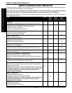
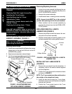
16
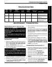
FRONT RIGGINGSPROCEDURE 1
F
R
O
N
T
R
I
G
G
I
N
G
S
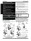
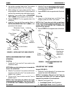
INSTALLING/ADJUSTING ADJUSTABLE
ANGLE FLIP-UP FOOTPLATES (FIGURE 4)
WARNING
When determining the angle of the footplates,
make sure the rear of the footplates do not in-
terfere with the movement of the front casters.
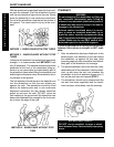
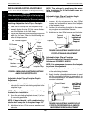
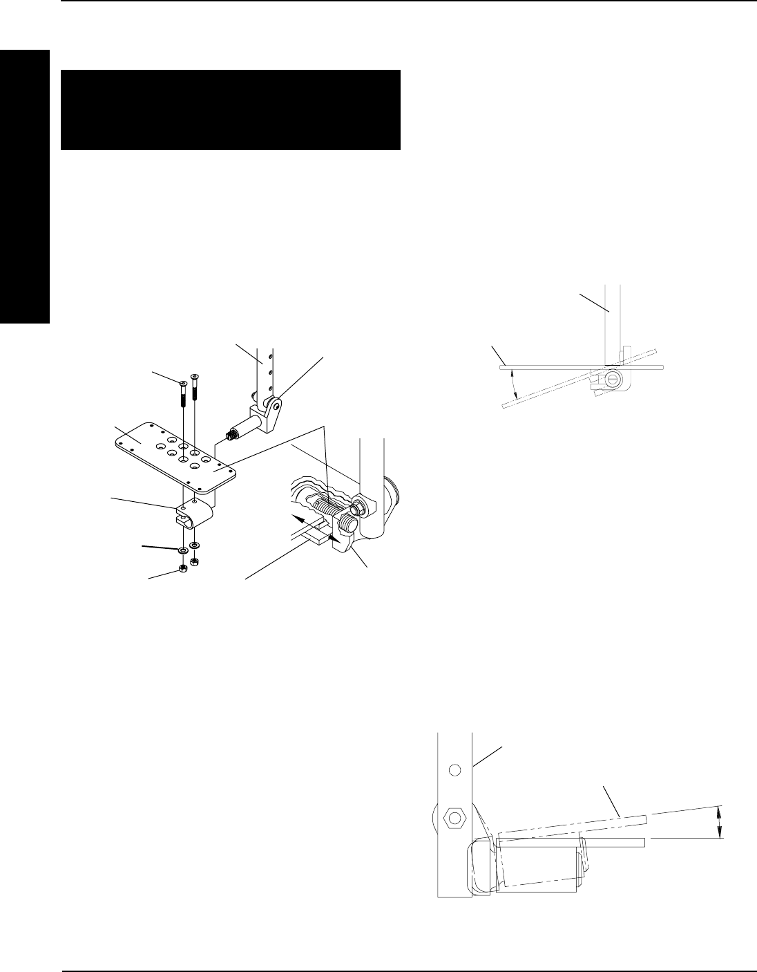
Installing Adjustable Angle Flip-up Footplate
1. Slide the half clamp over the footplate hinge.
2. Loosely tighten the two (2) flat screws that se-
cure the footplate to the half clamp.
3. Adjust the footplates to the necessary angle and
depth for the user. Refer to the following sec-
tions of this procedure.
Nylon
Adjustment
Screw
Footplate Hinge
Footplate
Hinge
Half
Clamp
Articulating
Footplate
Flat Screws
Half Clamp
Locknuts
Washers
FIGURE 4 - INSTALLING/ADJUSTING ADJUSTABLE
ANGLE FLIP-UP FOOTPLATES
Adjustable Angle Flip-up Footplate Depth
Adjustment
1. Remove the two (2) flat screws, washers and
locknuts that secure articulating footplate to the
footplate hinge.
NOTE: Observe the angle of the articulating
footplate for reinstallation.
2. Move the articulating footplate to one (1) of four
(4) mounting positions.
NOTE: If desired depth is still not obtained, ro-
tate the half clamp on the footplate hinge 180
o
.
3. Retighten the two (2) flat screws, washers and
locknuts.
NOTE: The settings for positioning the articu-
lating footplates on the half-clamps may vary
for each footplate.
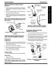
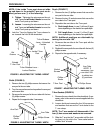
Adjustable Angle Flip-up Footplate Angle
Adjustment (FIGURES 4 AND 5)
1. Loosen, but do not remove the two (2) flat
screws and locknuts that secure the footplate
to the footplate hinge.
2. Position the articulating footplate to the neces-
sary angle to accommodate the user.
3. Retighten the two (2) flat screws and locknuts.
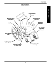
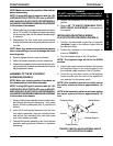
Side View Of
Footplate and
Footrest
Support.
Footrest
Support
Footplate
FIGURE 5 - ADJUSTABLE ANGLE FLIP-UP
FOOTPLATE ANGLE ADJUSTMENT
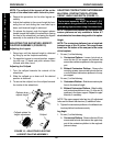
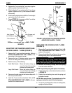
FIGURE 6 - ADJUSTABLE ANGLE FLIP-UP
FOOTPLATE PERPENDICULAR AND/OR
INVERSION/EVERSION ADJUSTMENT
Adjustable Angle Flip-up Footplate
Perpendicular and/or Inversion/Eversion
Adjustment (FIGURES 4 AND 6)
NOTE: It is not necessary to remove the footplate
to perform this adjustment.
1. Insert a flathead screwdriver through the half clamp
on the articulating footplate.
2. Slowly turn the nylon adjustment screw in or out
until the articulating footplate is perpendicular to
the footrest assembly or the desired inversion or
eversion is obtained.
Footplate
Footrest Support
Front View Of
Footplate and
Footrest
Support.
90
o
Footrest Support