


4 - 8
4.4 Wiring
4.4.2 External wiring
4
SETUP AND PROCEDURES BEFORE OPERATION
4.4.2 External wiring
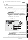
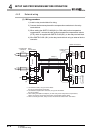
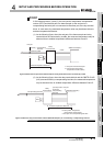
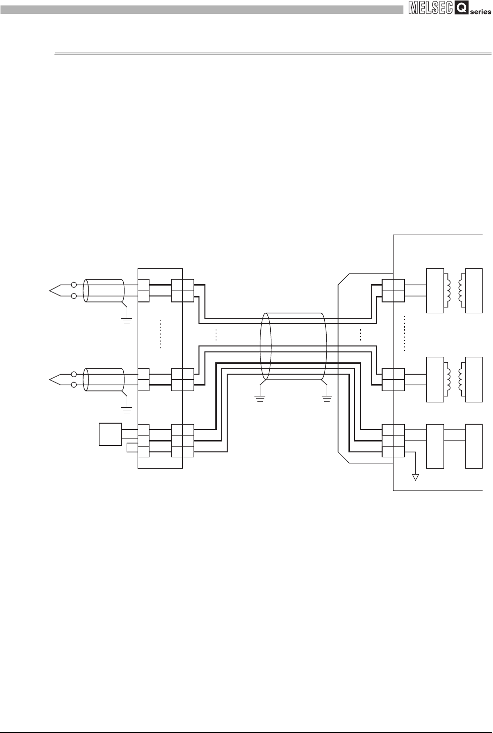
(1) Wiring procedure
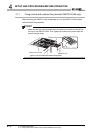
1) Install a relay terminal block for wiring.
2) Connect the thermocouple and the compensation conductors to the relay
terminal block.
3) When setting the Q68TD-G-H02(H01) to "With cold junction temperature
compensation", connect the cold junction temperature compensation resistor
(RTD), which is supplied with Q68TD-G-H02(H01), to the relay terminal block.
4) Wire Q68TD-G-H02 (H01) to the relay terminal block using an external device
connector.
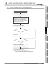
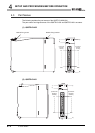
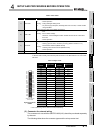
+
-
+
-
+
G
-
+
-
CH1
+
-
CH8
+
G
-
RTD
A1
B1
A15
B15
A20
B19
B20
Q68TD-G-H02(H01)
Cable(*1)
RTD
CH1
CH8
RTD
Compensation
conductors
(*2)
(*4)
(*3)
Relay
terminal block
External device
connector
Modulator
Demodulator
Modulator
Demodulator
Filter
Input amplifer
*1 Use shielded cables, and ground the shields.
Do not use compensation conductors.
*2 Use shielded compensation conductors, and ground the shields.
Do not use cables.
*3 When setting the Q68TD-G-H02(H01) to "With cold junction temperature compensation",
always connect the cold junction temperature compensation resistor (RTD).
*4 When connecting the RTD, always connect the terminals between RTD- and RTD G.