


4
SETUP AND PROCEDURES BEFORE OPERATION
4.1 Handling Precautions
4 - 1
1
OVERVIEW
2
SYSTEM
CONFIGURATION
3
SPECIFICATIONS
4
SETUP AND
PROCEDURES BEFORE
OPERATION
5
UTILITY PACKAGE (GX
CONFIGURATOR-TI)
6
PROGRAMMING
7
ONLINE MODULE
CHANGE
8
TROUBLESHOOTING
CHAPTER4 SETUP AND PROCEDURES BEFORE
OPERATION
4.1 Handling Precautions
(1) Do not drop or give a strong impact to the case.
(2) Do not remove the printed-circuit board of the module from the case.
Doing so may cause a failure.
(3) Be careful to prevent foreign matters such as cutting chips or wire chips
from entering the module.
Such foreign matter can cause a fire, failure, or malfunction.
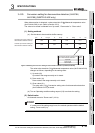
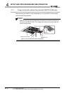
(4) A protective film is attached to the module top to prevent foreign matter
such as wire chips from entering the module during wiring.
Do not remove the film during wiring.
Be sure to remove it for heat dissipation before system operation.
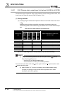
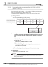
(5) Tighten the screws such as module fixing screws within the following
ranges.
Undertigtening can cause drop of the screw, short circuit or
malfunction.
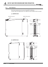
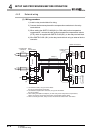
* 1 The module can be easily fixed onto the base unit using the hook at the top of the module.
When using the Q68TD-G-H02(H01) in an environment of frequent vibrations, fix the module with a
module fixing screw.
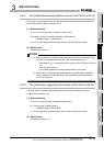
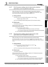
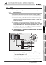
(6) To mount the module, while pressing the module mounting lever located
in the lower part of the module, fully insert the module fixing projection
into the hole in the base unit and press the module until it snaps into
place.
Incorrect module mounting may cause a malfunction, failure, or drop of
the module.
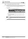
After mounting the module to the base unit, fix the module with a
module fixing bracket. (Q68TD-G-H02 only) (Refer to Section 4.1.1)
When using the Q68TD-G-H01 in an environment of frequent vibrations,
fix the module with a module fixing screw. (Q68TD-G-H01 only)
(7) Always make sure to touch the grounded metal to discharge the
electricity charged in the body, etc., before touching the module.
Failure to do so may cause a failure or malfunctions of the module.
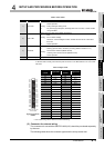
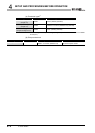
Table 4.1 Tightening torque
Screw location Tightening torque range
Module fixing screw (M3 screw)
*1
0.36 to 0.48N•m
Connector screw (M2.6 screw) 0.20 to 0.29N•m