3
SPECIFICATIONS
3.4 Buffer Memory
3.4.16 Disconnection state monitor flag (Un\G49) (Q68TD-G-H01only)
3 - 51
1
OVERVIEW
2
SYSTEM
CONFIGURATION
3
SPECIFICATIONS
4
SETUP AND
PROCEDURES BEFORE
OPERATION
5
UTILITY PACKAGE (GX
CONFIGURATOR-TI)
6
PROGRAMMING
7
ONLINE MODULE
CHANGE
8
TROUBLESHOOTING
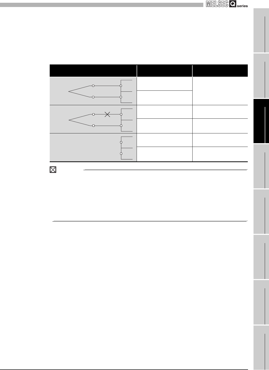
(3) Relationship between the Disconnection state monitor flag and
conversion enable/disable setting.
The following table shows the relationship between the Disconnection state monitor
flag and conversion enable/disable setting.
POINT
(1) Always set “Disable” for any channel where no thermocouple or
compensating lead wire is connected.
If “Enable” is set, the bit of the corresponding channel in Disconnection
detection flag (Un\G49) turns on (changes to “1”).
(2) For wiring of a thermocouple or compensating lead wire, refer to Section 4.4.
(3) For troubleshooting of disconnection state check, refer to Section 8.2.7.
Table 3.15 Relationship between conversion enable/disable setting and Disconnection detection flag
Connection state
Conversion enable/disable
setting
Disconnection state
monitor flag
Enable
OFF
Disable
Enable ON
Disable OFF
Enable ON
Disable OFF
Without disconnection
+
-
With disconnection
+
-
Without connection
+
-


