


66
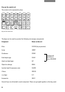
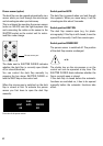
Checking of various microscope components
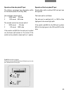
Engage or disengage the filters (54.16) accord-
ing to the required brightness.
If necessary, disengage the Bertrand lens by
turning the knurled knob (54.22), pos. 1.
Disengage the analyser (55.21), if necessary, by
pulling it out partway.
Disengage the filter systems, if necessary, by
rotating the turret (55.11).
Push in the switch rod(s) for the beamsplitter
(54.23).
Clamp the transmitted light illumination arm with
the knurled wheel (5.1).
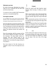
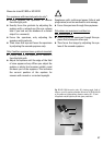
Operation of L objectives with correction mount
Roughly set the correction mount to the thick-
ness of the base of the vessel on the stage by
turning the knurled ring. Focus the specimen
with the coarse and fine drive. Then operate the
correction mount until you achieve the greatest
image contrast, using the fine focus if neces-
sary.
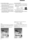
Setting the tubes and eyepieces
Eyeglass wearers must remove (for 10x/25) or
push back (for 10x/20 and 10x/22) the anti-glare
protection of the eyepieces, but it should always
be left on for viewers not wearing eyeglasses.
● Set the interpupillary distance on the tube by
pulling apart or pushing together the eyepiece
tubes until only one image can be seen with
both eyes.
● Note your personal interpupillary distance.
● If using ergotubes, set the viewing angle
(15° –50°) as well by tilting the binocular
viewing port. To avoid symptoms of fatigue,
vary the viewing angle from time to time.
● Close any tube exits you are not using to
prevent stray light disturbing the image.
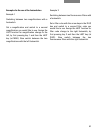
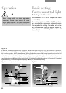
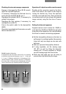
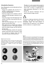
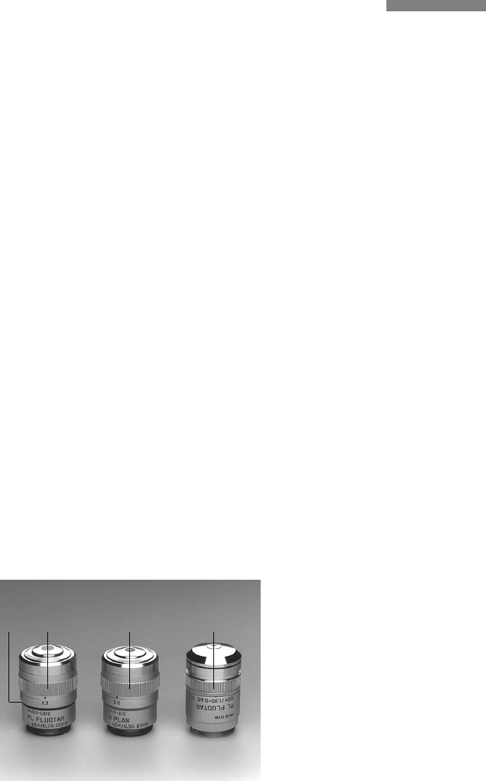
Fig. 56␣ ␣ Examples of objectives
1, 2 Objectives with correction mounts (Corr) for adjusting
to different vessel base thicknesses (e.g. 0.1 – 1.3 mm and
0 – 2 mm), 3 Objective with built-in iris diaphragm (1.30 =
maximum aperture, 0.60 = minimum aperture), 4 Magnifica-
tion colour code, 5 Knurled ring for adjusting the correction
mount, 6 Knurled ring for adjusting the built-in diaphragm
55
123
64