


23
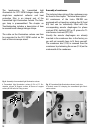
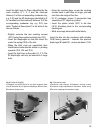
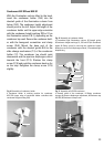
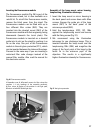
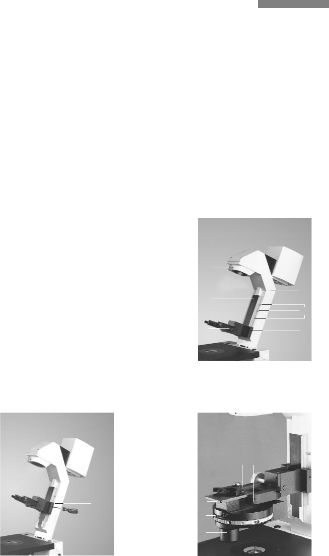
Fig. 15 Assembly of condenser holder
1 Transmitted light illumination column, 2 Dovetail guide,
3 Condenser height markings S1, S23 and S70, 4 Condenser
holder, 5 Clamp screw for securing the condenser holder,
6 Clamp screw for field diaphragm module, 7 Transmitted light
lamphousing
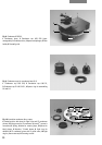
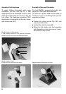
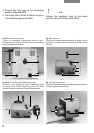
Fig. 16 Assembly of condenser holder
1 Condenser holder in working position for condenser
0.53 S23 (upper edge of condenser holder coincides with
condenser height marking S23)
Fig. 17 Assembly of 0.53 S23 condenser
1 Dovetail guide of the condenser, 2 Sliding condenser
changer, 3 Aperture diaphragm adjustment, 4 Condenser top
0.53 S23, 5 Condenser clamp screw
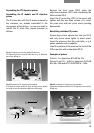
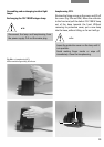
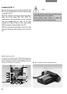
Condensers 0.53 S23 and 0.90 S1
With the illumination column tilted to the back,
insert the condenser holder (15.4) into the
dovetail guide of the illumination column from
below (15.2). The condenser height adjustment
should point to the left. Adjust the height of the
condenser holder until its upper edge coincides
with the condenser height marking S23 or S1 on
the illumination column (16.1), depending on the
condenser top used. Secure the condenser hold-
er with the hexagonal screwdriver and clamp
screw (15.5). Mount the base part of the
condenser with the dovetail guide (8.6) to the
slide change mechanism (7.1) of the condenser
holder (17). The condenser top should point
downwards and the aperture diaphragm control
towards the front (17.3). Slacken the clamp
screw (17.5) and push the condenser back as far
as the stop. Retighten the clamp screw (17.5)
slightly.
5
3
1
4
2
6
7
1
4
3
1
2
5