


19
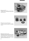
Insert the light rings for Phaco (identified by the
code numbers 0, 1, 2, 3 and the intercept
distance S of the corresponding condenser top,
e. g. 2 S1) and the DF diaphragm (identified by D
for darkfield and the intercept distance S of the
corresponding condenser top, e. g. D S1, see
table “Technical Description”) in the slots of the
disc as follows:
– Slightly unscrew the two centring screws
(10.11) using the supplied centring key (12.1).
– Insert the diaphragms so that the mount fits
under the spring (10.3) of the slot.
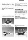
– When the light rings are assembled, their
identification code must be visible i.e. pointing
upwards (12.3, 12.4 and 12.5).
– Insert the light rings in the order 0, 1, 2, 3. The
DF diaphragm can only be inserted in a large
hole.
– Using the centring keys, screw the centring
screws back in until they no longer protrude
over the outer edge of the disc.
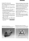
– Fit IC condenser prisms if appropriate (see
assembly of ICT objective prisms).
– Insert the plastic labels (10.7) in the disc
(12.2), allocating them to the corresponding
diaphragms.
– Mark any empty holes with white labels.
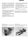
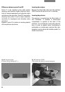
Insert the disc into the condenser with notches
(10.6) facing upwards – towards the aperture
diaphragm (6.3 and 8.4) – and screw down (11.4).
3
4
1
2
5
3
2
4
5
1
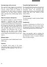
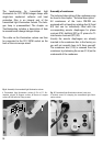
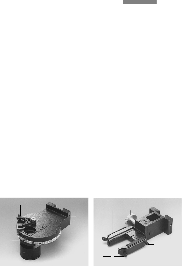
Fig. 7
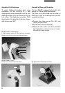
Condenser holder
1
Condenser slide changer, 2 Condenser centring screws,
3 Condenser height adjustment, 4 Condenser clamp screw,
5 Screw for clamping the condenser holder
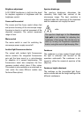
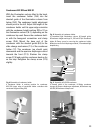
Fig. 6 Condenser 0.30 S70
1
Condenser top 0.30 S70 (not for use with condenser base
(8.1)), 2 Condenser disc, 3 Aperture diaphragm, 4 Filter holder,
5 Condenser clamp screw