


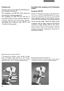
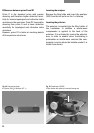
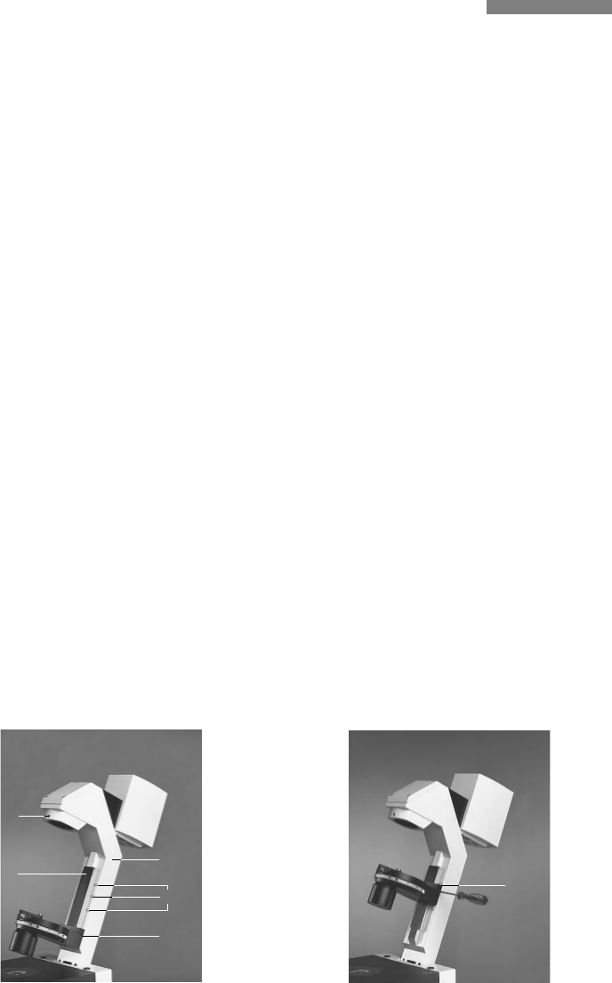
22
Assembly of the condensers to the illumination
column
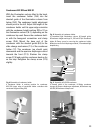
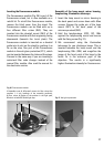
Condenser 0.30 S70
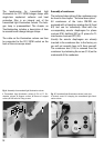
Tilt the TL illumination column to the back (13.1).
Insert the condenser 0.30 S70 (13.4) from below
into the dovetail guide of the illumination column
(13.2), with the condenser top pointing towards
the microscope stage. Adjust the height of the
condenser until its upper edge is flush with the
condenser height marking S70 on the illumi-
nation column. Secure the condenser with the
supplied hexagonal screwdriver. Erect the TL
illumination column.
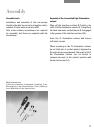
Fig. 13 Assembly of condenser 0.30 S70
1
Transmitted light illumination column (tilted), 2 Dovetail
guide, 3 Condenser height markings S1, S23 and S70,
4 Condenser 0.30 S70, 5 Condenser clamp screw, 6 Field
diaphragm clamp screw, 7 Transmitted light lamphousing
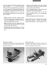
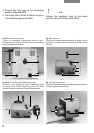
Fig. 14 Assembly of condenser 0.30 S70
1 Condenser 0.30 S70 in working position (upper edge of
condenser is flush with condenser height marking S70)
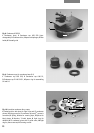
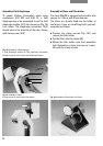
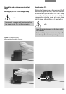
Condenser top
The base and top of condenser 0.30 S70 form a
self-contained unit (Fig. 6).
The condenser top 0.30 S70 (13.4) cannot be
used with the condenser base (8.1).
The condenser top 0.53 S23 (8.2 and 9.1) is
screwed straight on to the condenser base (8.1).
A spacer ring (9.4 and 11.3) must be used for
assembling the condenser tops 0.90 S1 and
P 1.40 OIL S1 (9.2 and 9.3).
3
1
5
4
2
6
7
1