


27
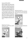
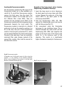
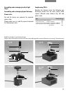
Inserting the fluorescence module
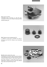
The fluorescence module (Fig. 26) is part of the
fluorescence stand, but is also available as a
retrofit kit. To retrofit the fluorescence module,
remove the blind cover from the stand. The
fluorescence module can be fitted with up to
four different filter cubes (26.3). They are
inserted into the dovetail mount (26.2) of the
fluorescence module with their engraving facing
downwards (towards the turret plate). The
fluorescence module is inserted on a dovetail
guide into its slot on the stand by pushing it as
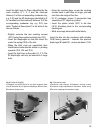
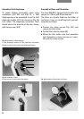
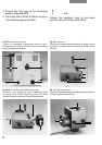
far as the stop. One part of the fluorescence
module is the anti-glare protection (27.1), which
can be inserted between the tube and the stage.
Proceed in the same way if you are inserting a
motorised filter cube changer instead of the
manual filter module. Also read the manual for
the electronic version.
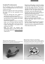
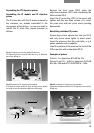
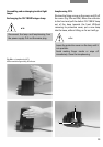
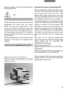
Assembly of the lamp mount, mirror housing,
lamphousing, illumination telescope
1. Insert the lamp mount or mirror housing in
the back panel and screw down with Allen
screws. Engage the guide pin of the lamp
mount (29.1) in the back panel of the
microscope stand (28.2).
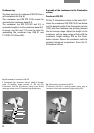
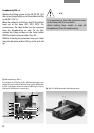
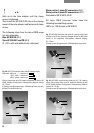
2. Hold the lamphousings 107/2, 107, 106 z
against the lamphousing mount and secure
with the fixing screw (Fig. 31).
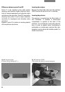
3. We recommend using the illumination
telescope for gas discharge lamps. This is
inserted between the lamp mount and the
lamphousing 106 z (30.4) and magnifies the
image of the focal point of the lamp by the
factor 2x in the entrance pupil of the
objective. This results in a significantly
higher illumination intensity for fluorescence.
Fig. 26 Fluorescence module
1 Rotatable turret, 2, 4 Dovetail mounts for filter cubes (the
numbers 1␣ –␣ 4 are markings of the assembly positions),
3 Filter cubes, 4 Display of the position in the light path,
5 Switch rod with BG 38 and light stop
2
1
4
5
3
Fig. 27 Anti-glare protection