


21
Assembly of IC condenser prisms
The IC condenser prisms are assembled at the
factory. The following steps are only necessary
in case of a retrofit:
Remove the condenser disc (11.5) by slackening
the screw (11.4) on the underneath of the
condenser.
– Using the centring keys (12.1), slightly un-
screw the two centring screws (10.11).
– IC condenser prisms can only be inserted into
the large holes of the condenser disc which
have guide grooves (10.2).
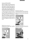
– Insert the IC condenser prisms in ascending
order, e. g. K1, K2 and so that the mount fits
under the spring (10.3) in the slot and the
2 guide cams engage in the grooves of the
condenser disc (10.2).
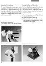
– When the prisms are inserted, their
identification code, e. g. K10, must be visible
and pointing towards the
centre of the disc
(12.6 and 12.7).
– Using the centring keys, screw the centring
screws back in until they no longer protrude
over the outer edge of the disc. The prism is
adjusted with the left centring screw only (see
operation of ICT). The right centring screw
must never restrict the adjustment range.
– Assemble the light rings and DF diaphragm if
appropriate (see previous section).
– Insert the label plates (10.7) corresponding to
the relevant IC condenser prism.
– Mark any empty holes with white labels.
– Remove any finger marks or dust on the
prisms carefully.
– Put the condenser disc back in the condenser
with the notches (10.6) facing upwards –
towards the aperture diaphragm (6.3 and 8.4).
Screw down the disc (11.4).
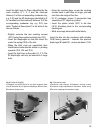
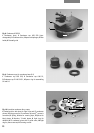
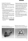
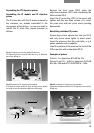
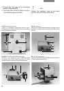
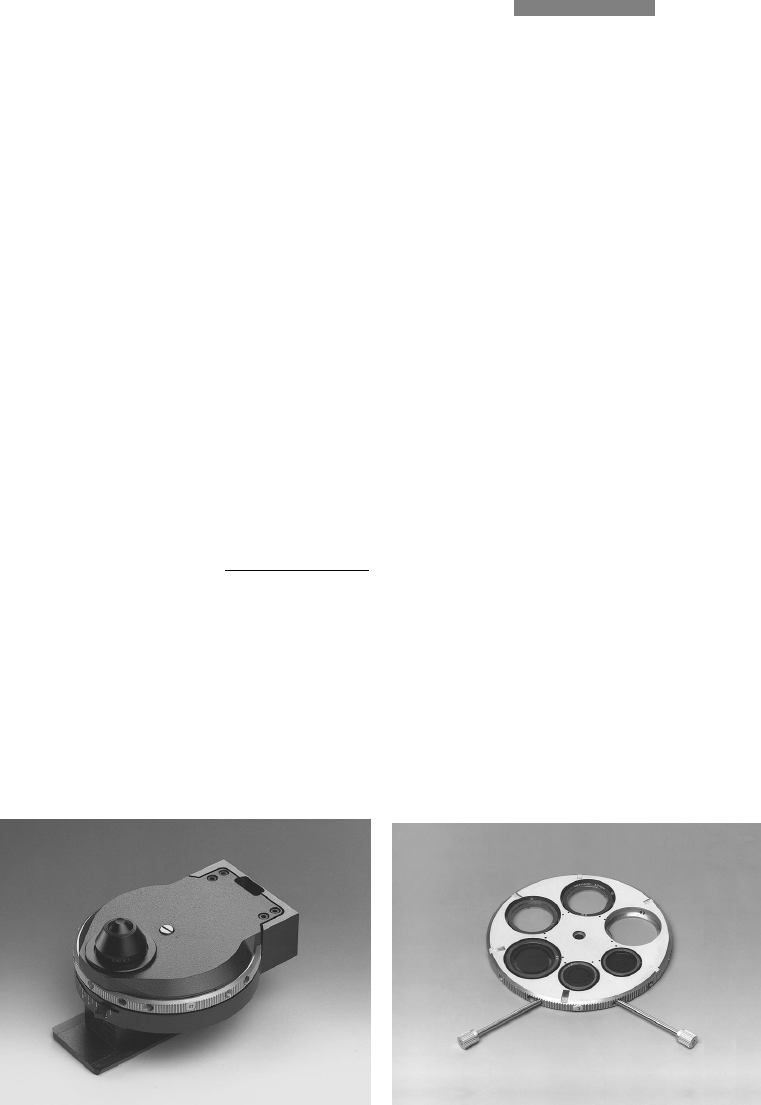
Fig. 12 6-position condenser disc, fully equipped
1 Centring keys for centring screws (in working position),
2 Label plates, 3, 4 Light rings for phase contrast, 5 Light ring
for darkfield, 6, 7 IC condenser prisms, 8 Hole for brightfield
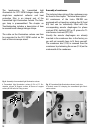
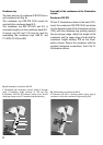
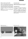
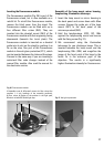
Fig. 11 Condenser 0.90 S1 (bottom up)
1 Condenser base, 2 Condenser top 0.90 S1, 3 Spacer ring,
4 Fixing screw for condenser disc, 5 Condenser disc
6
5
4
3
8
7
11
2