


Performance Procedures
4-36 Testing the Monitor
Serial
Interface
and Nurse
Call Signal
Test
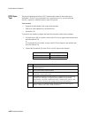
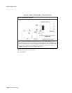
Perform the following procedure to test the serial port voltages. The test is qualitative and
only verifies that the serial interface port is powered correctly, and that the Nurse Call signal
is operational. The serial connector is a male DB-9 located on the monitor’s rear panel,
identified by the RS-232 symbol.
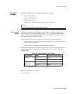
Tools Needed:
• Clinical Dynamics Corp - SmartSat simulator (with Nellcor simulator cable)
•SpO
2
adapter cable (M1943A)
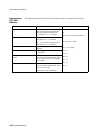
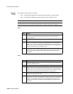
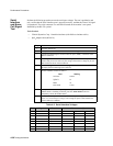
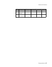
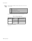
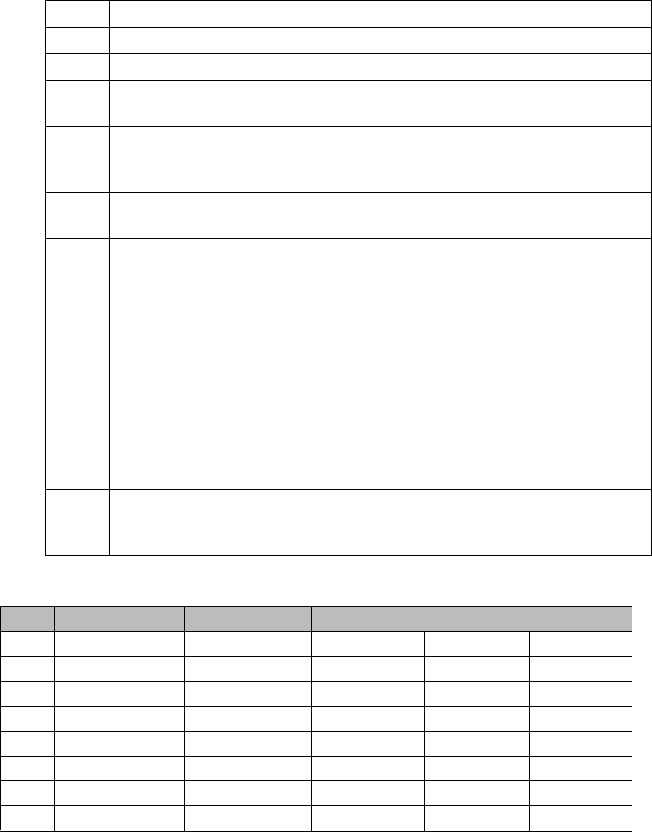
Table 4-2. Serial Interface Voltages
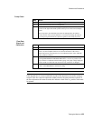
Step Action
1 Turn the monitor On.
2 Set up the DMM with the function set to VDC at a range of 10 volts.
3 Connect the DMM negative lead to connector pin 5 (GND), or the shell of the
RS-232 connector.
4 Referring to Table 4-2, Serial Interface Voltages, connect the DMM positive
lead to each pin in turn, and verify the voltage values listed. Voltage for pin 9 is
that listed from the No Alarm condition.
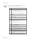
5 Connect SpO
2
simulator cable to the SpO
2
adapter cable. Connect the cable to
the SpO
2
patient monitoring input connector.
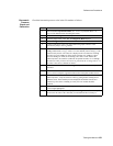
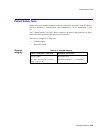
6 Set the simulator switches as follows:
7 Verify that the monitor is responding to the SpO
2
simulator signal and the
audible alarm is sounding. If desired, press the Alarm Silence button to
temporarily silence the audible alarm.
8 Connect the DMM positive lead to pin 9 and verify the voltage value listed in
Table 4-2, Serial Interface Voltages. The voltage for pin 9 is that listed for the
Alarm Underway condition.
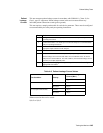
Pin Signal Direction Measurement (V)
Min. Typical Max.
1 not used -0.4 0.0 0.4
2 RXD <<< input -0.4 0.0 0.4
3 TXD<<< output -5.0 -7.0 -15.0
4 DTR<<< output 5.0 7.0 15.0
5 GND -0.4 0.0 0.4
6 DSR<<< input -0.4 0.0 4.0
7 RTS>>> output 5.0 7.0 15.0
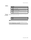
Item Setting
Oximeter Nellcor
SpO
2
%
81
BPM 36
Pulse Mod 0.50%