


Part 2 Isolating and Solving Monitor Problems
6-8 Troubleshooting
Isolating the
Defective
Component
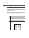
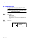
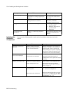
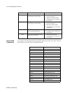
You can use the following table to isolate and solve problems which may occur in the
monitor.
"SpO
2
Noisy Signal" Excessive patient movement or electrical
interference are causing irregular pulse
patterns.
Try to reduce patient movement,
or to relieve the cable strain on
the sensor.
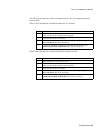
"SpO
2
Non-Pulsatile" Pulse is too weak or is not detectable, or
the application site is too thin.
Change the application site of
the sensor, or stimulate
circulation at the current site.
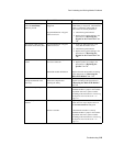
"SpO
2
Transduc Malf" Sensor is malfunctioning. 1. Change the SpO
2
sensor as
soon as possible.
2. Return the faulty sensor to
your biomedical
department.
"Temperature Probe
Disconnect"
Monitor is not detecting temperature
reading.
Check that the temperature probe
is properly connected to the
monitor.
Message Cause of Failure Remedy
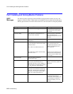
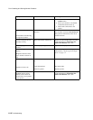
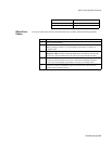
Symptom Cause of Failure Remedy
The battery symbol is not
displayed
A battery is not present in the
monitor, the battery is defective,
or there is a bad connection.
Install a charged battery (see “Removing
the Battery” on page 7-4). If a battery is
already present, remove it and refit the
battery making sure to push is completely
into position. Check the connection wires
to make sure wires are secured to battery.
Some or all numerics or
waves are not displayed
Parameters are switched off.
No accessories are connected.
Switch parameters on.
Connect the required accessories. If
connections are secure, replace the suspect
accessory.
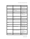
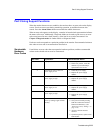
Monitor screen appears dim Brightness not properly adjusted.
Display backlight tube worn.
Adjust brightness using Contrast button.
Replace backlight tube according to
instructions in “Replacing the Backlight
Tube” on page 7-9.
Monitor screen is blank Display backlight tube worn or
loose connection.
Main PCB module malfunction.
1. Check the backlight tube connector
2. Replace the backlight tube
Replace the Main PCB module according
to instructions in
“Removing the Main
PCB Module” on 7-12
.