


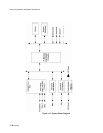


Theory of Operation and System Architecture
11-8 Training
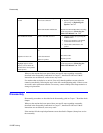
The Contrast button operates in conjunction with the navigation wheel to determine the
apparent contrast setting in the display. Changing the contrast is a change in the viewing
angle. Outputs of the button and wheel are connected to the processor.
Momentarily pressing the button sets the contrast to mid-range, factory-default value.
Momentarily pressing of the button, followed within 3 seconds by a rotation of the wheel are
processed to vary the contrast of the display. When there has been no wheel rotation for 3
seconds, the contrast control function is terminated by the processor. The contrast control
function is also terminated if the wheel is pressed any time within this 3 second interval.
Operation of the Volume button accomplishes similar functions for the volume of the heart
rate audible tone as the display contrast control button does for the display. Pressing this
button, enables the wheel to vary the tone volume.
Navigation
Wheel
This is a rotating, push-switch wheel. The associated wheel circuitry generates a pulse when
pressed and generates a digitally encoded pair of quadrature signals whose relative
magnitudes and polarities represent the angular position of the wheel. These outputs are
connected to the processor where they are interpreted as required for the functions involved.
Successive angular positions determine the direction of wheel rotation.
In addition to the functions performed when in conjunction with the keypad as described
above, the wheel operates in conjunction with the display to select menus and lists of
parameter variables.
RS-232 I/O This is a rear panel 9-pin connector providing interfaces with other computer systems or
equipment. The driver for this "port" is a Universal Asynchronous Receive-Transmit (UART)
integrated circuit that interfaces this port with the microprocessor. The baud rate for this serial
transmission function is programmable from 1200 baud to 38.4 kilobaud.
Pin number 9 of the RS-232 connector is reserved for a Nurse Call signal. The nurse call
signal reacts when a low, medium, or high level alarm is activated.
Defib Sync
Pulse
The rear panel connector for the Defib Sync Pulse is keyed so that the connection of a cable
can be detected by the processor. When a connection is detected, the processor software
initiates the generation by hardware of a TTL-compatible pulse capable of driving 1 TTL load
over a three-meter cable with less than 200 pF capacitance.
The defib pulse is triggered by the detection of the R-wave in the QRS sequence of the ECG
wave-form complex. The pulse signal is active for 100 ±10 ms
.
Speaker The speaker is capable of providing 73 dBA of volume at a distance of one meter during
alarm conditions. The processor drives the speaker in different patterns as specified for the
different alarm priorities and conditions. Refer to the C3 Instructions for Use guide for
descriptions of alarm responses.