


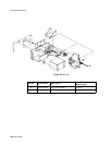
About the RS-232 Interface
10-4 RS-232 Interface
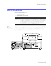
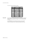
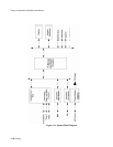
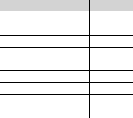
Pin connections for the 9-pin connector are as follows:
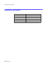
Nurse-Call Pin 9 of the RS-232 serial interface connector provides an Alarm Out signal. Any time there is
any alarm condition active in the monitor, and if the Nurse Call Signal option in the Setup
Menu is On, pin 9 goes to plus RS-232 level voltage (> +5 VDC). The alarm delay shall be
< 0.5 seconds.
If in the Setup Menu, the Nurse Call Signal option is Off, pin 9 is always at the minus
RS-232 level voltage. In order to make use of the Alarm Out signal, pin 9 should be
connected to a high-impedance circuit (>1000) and protected against transient voltages.
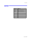
Table 10-1. RS-232 Serial Interface Connections
Pin # Signal Direction
1 not used
2 Rx data input
3 Tx data output
4 DTR output
5 Signal Ground input/output
6 DSR input
7 RTS output
8 CTS input
9 Alarm Out output