The calibration parameters C0, C100, and C400 can be adjusted to optimize the
accuracy. These password-protected parameters are accessed from the CALI
-
BRATION function of the SYSTEM menu.
9.1.2 PRT Calibration Procedure
Calibration requires adjustment of the C0, C100, and C400 parameters at three
specific input resistances. If the resistances used are approximately 0Ω, 100Ω
and 400Ω respectively the adjustments are independent and the procedure is
simple. The order in which the adjustments are performed is important. The ad
-
justment of the C400 parameter must be done last as the adjustments of C0 and
C100 affect the measurement at 400Ω but C400 does not affect the measure
-
ments at 0Ω or 100Ω. Each channel must be calibrated. Set the conversion type
to RES to display resistance (see Section 7.2.1.5) and the RANGE parameter to
100Ω. The calibration should be performed with a four-wire connection and
with the probe wiring parameter set to four-wire (see Section 6.4, Connecting
the Probe). The accuracy required of the resistance standards is 1/4 of the in
-
strument accuracy; that is ±0.000125Ω at 0Ω, ±0.0006Ω ( 6 ppm) at 100Ω,and
±0.0024Ω (6 ppm) at 400Ω. The recommended procedure is as follows:
1.
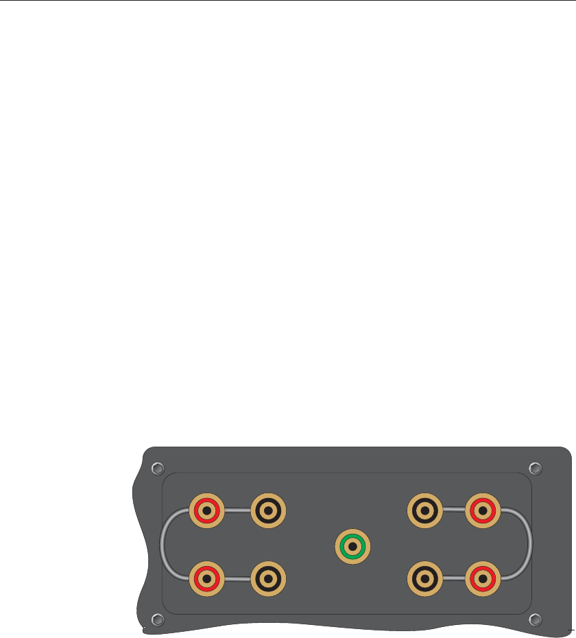
Connect a 0Ω resistor to the input and measure its resistance. If a short-
ing wire is used the wire should run from the C2 terminal to the C1 ter-
minal to the P1 terminal to the P2 terminal (See Figure 50). Note the
average error in the measurement. Adjust the C0 parameter by subtract-
ing the measured error. For example, if the input is exactly 0.0000 and
the readout shows –0.0011, adjust the C0 parameter by adding 0.0011.
2.
Connect a 100Ω resistor (6 ppm accuracy) to the input and measure its
resistance. Note the average error in the measurement. Adjust the C100
parameter by subtracting the measured error. For example, if the input is
exactly 100.0000Ω and the readout shows 100.0295Ω, adjust the C100
parameter by subtracting 0.0295.
1529 Chub-E4 Thermometer Readout
User’s Guide
132
C1 C2
P1 P2
C2 C1
P2 P1
Figure 50 Using a Shorting Wire


