


65
Reference Manual
00809-0100-4102, Rev AA
Section 5: Operation and Maintenance
May 2013
Operation and maintenance
For transmitters that are field installed, the manifolds discussed in “Rosemount 304, 305 and
306 integral manifolds” on page 47 allow the differential transmitter to be zeroed using the zero
trim function. Both 3-valve and 5-valve manifolds are discussed. This field calibration will
eliminate any pressure offsets caused by mounting effects (head effect of the oil fill) and static
pressure effects of the process.
Determine the necessary trims with the following steps.
1. Apply Pressure
2. Check digital pressure, if the digital pressure does not match the applied pressure,
perform a digital zero trim. See “Sensor Trim” on page 68.
Trimming with configuration buttons
Local configuration buttons are buttons located inside the housing of the transmitter. To access
the buttons, remove the housing cover.
Digital Zero Trim (DZ): Used for performing a sensor zero trim. See “Recommended
Calibration Tasks” on page 64 for trim instructions.
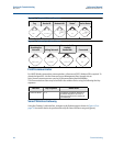
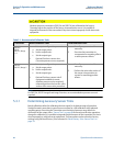
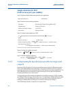
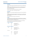
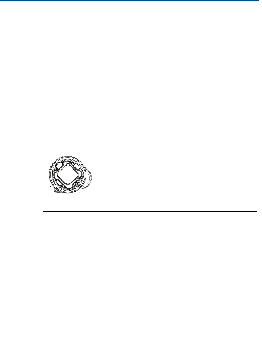
Figure 5-1 shows the location of the digital zero button.
Figure 5-1. Digital zero button location
A. Digital zero button
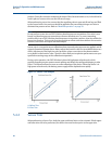
5.3.2 Determining calibration frequency
Calibration frequency can vary greatly depending on the application, performance
requirements, and process conditions. Use the following procedure to determine calibration
frequency that meets the needs of your application.
1. Determine the performance required for your application.
2. Determine the operating conditions.
3. Calculate the Total Probable Error (TPE).
4. Calculate the stability per month.
5. Calculate the calibration frequency.
Digital Zero
Trim
A