


38
Reference Manual
00809-0100-4102, Rev AA
Section 3: Installation
May 2013
Installation
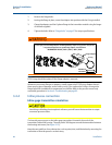
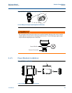
Bolt installation
Only use bolts supplied with the Rosemount 2051 or sold by Emerson Process Management as
spare parts. When installing the transmitter to one of the optional mounting brackets, torque
the bolts to 125 in-lb. (0,9 N-m). Use the following bolt installation procedure:
1. Finger-tighten the bolts.
2. Torque the bolts to the initial torque value using a crossing pattern.
3. Torque the bolts to the final torque value using the same crossing pattern.
Torque values for the flange and manifold adapter bolts are as follows:
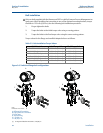
Table 3-2. Bolt Installation Torque Values
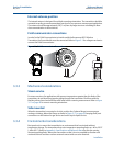
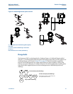
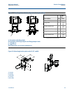
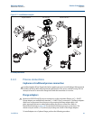
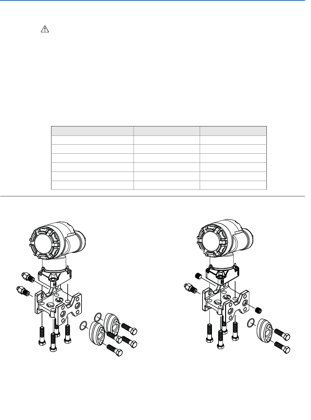
Figure 3-6. Traditional flange bolt configurations
A. Differential Transmitter
B. Gage/Absolute Transmitter
C. Drain/Vent
D. Vented fitting
E. 1.75 (44) × 4
F. 1.50 (38) × 4
(1)
Bolt Material Initial Torque Value Final Torque Value
CS-ASTM-A445 Standard 300 in.-lb (34 N-m) 650 in.-lb (73 N-m)
316 SST—Option L4 150 in.-lb (17 N-m) 300 in.-lb (34 N-m)
ASTM-A-193-B7M—Option L5 300 in.-lb (34 N-m) 650 in.-lb (73 N-m)
Alloy K-500—Option L6 300 in.-lb (34 N-m) 650 in.-lb (73 N-m)
ASTM-A-453-660—Option L7 150 in.-lb (17 N-m) 300 in.-lb (34 N-m)
ASTM-A-193-B8M—Option L8 150 in.-lb (17 N-m) 300 in.-lb (34 N-m)
(1) For Gage and Absolute Transmitters: 150 (38) x 2
AB
C
C
D
C
E
E
FF
Note
Dimensions are in inches