


5
Reference Manual
00809-0100-4102, Rev AA
Section 1: Introduction
May 2013
Introduction
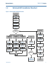
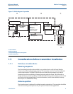
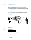
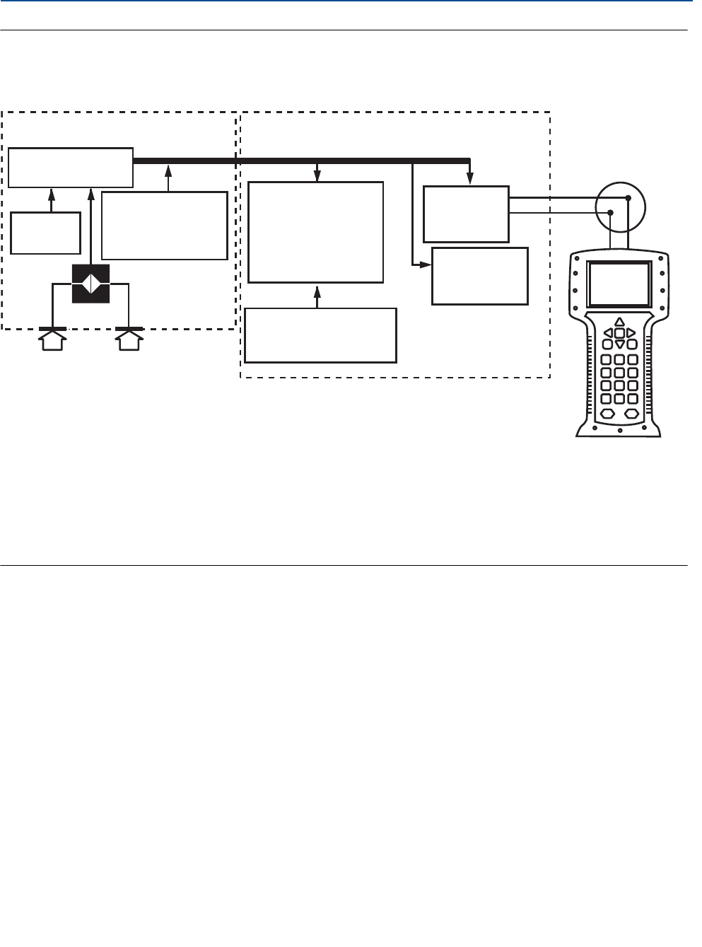
Figure 1-3. Block diagram of operation
A. Sensor Module
B. Electronics Board
C. WirelessHART Signal to Control System
D. Field Communicator
1.5 Considerations before transmitter installation
1.5.1 Wireless considerations
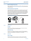
Power up sequence
The Power Module should not be installed on any wireless device until the Smart Wireless
Gateway is installed and functioning properly. This transmitter uses the Green Power Module
(order model number 701PGNKF). Wireless devices should also be powered up in order of
proximity from the Smart Wireless Gateway, beginning with the closest. This will result in a
simpler and faster network installation. Enable Active Advertising on the Gateway to ensure that
new devices join the network faster. For more information, see the Smart Wireless Gateway
Manual (Doc. No. 00809-0200-4420).
Antenna position
The internal antenna is designed for multiple mounting orientations. The transmitter should be
mounted according to best practices for your pressure measurement application.
ABC
D
Signal Processing
Tem p.
Sensor
Sensor Module
Memory
Microprocessor
Sensor linearization
Rerange
Diagnostics
Engineering units
Communication
Memory
Configuration
Local HART
Handheld
Communicator
WirelessHART
Communication