34
Reference Manual
00809-0100-4102, Rev AA
Section 3: Installation
May 2013
Installation
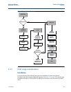
Tilting of the transmitter may cause a zero shift in the transmitter output, but can be eliminated
by performing a trim procedure.
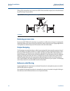
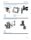
Figure 3-3. Draft range installation example
A. Isolators
Reducing process noise
Rosemount 2051CD0 draft transmitters are sensitive to small pressure changes. Increasing the
damping will decrease output noise, but will further reduce response time. In gage applications,
it is important to minimize pressure fluctuations to the low side isolator.
Output damping
The Damping command introduces a delay in processing which increases the response time of
the transmitter; smoothing variations in output readings caused by rapid input changes. In the
Rosemount 2051 Wireless pressure transmitter, damping only takes effect when the device is
placed in high power refresh mode and during calibration. In normal power mode, the effective
damping is 0. Note that when the device is in high power refresh mode, battery power will be
depleted rapidly. Determine the appropriate damp setting based on the necessary response
time, signal stability, and other requirements of the loop dynamics of your system. The damping
value of your device is user selectable from 0 to 60 seconds.
Reference side filtering
In gage applications it is important to minimize fluctuations in atmospheric pressure to which
the low side isolator is exposed.
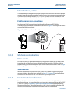
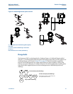
One method of reducing fluctuations in atmospheric pressure is to attach a length of tubing to
the reference side of the transmitter to act as a pressure buffer.
A


