


50
Reference Manual
00809-0100-4102, Rev AA
Section 3: Installation
May 2013
Installation
Note
If using thread tape, be sure the thread tape does not strip when the manifold assembly is
started.
5. Wrench tighten manifold into process connection. (Note: Minimum toque value is 425
in-lbs)
6. Count how many threads are still showing. (Note: Minimum engagement is 3
revolutions)
7. Subtract the number of threads showing (after tightening) from the total threads to
calculate the revolutions engaged. Further tighten until a minimum of 3 rotations is
achieved.
8. For block and bleed manifold, verify the bleed screw is installed and tightened. For
two-valve manifold, verify the vent plug is installed and tightened.
9. Leak-check assembly to maximum pressure range of transmitter.
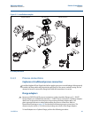
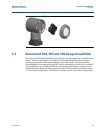
3.5.3 Rosemount 304 Conventional Manifold installation
procedure
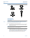
To install a 304 Conventional Manifold to a 2051 Wireless transmitter:
1. Align the Conventional Manifold with the transmitter flange. Use the four manifold
bolts for alignment.
2. Finger tighten the bolts, then tighten the bolts incrementally in a cross pattern to final
torque value. See “Flange bolts” on page 37 for complete bolt installation information
and torque values. When fully tightened, the bolts should extend through the top of
the sensor module housing.
3. If applicable, install flange adapters on the process end of the manifold using the
1.75-in. flange bolts supplied with the transmitter.
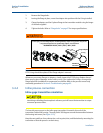
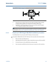
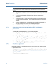
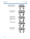
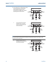
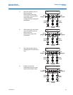
3.5.4 Manifold operation
Improper installation or operation of manifolds may result in process leaks, which may cause
death or serious injury.
Always perform a zero trim on the transmitter/manifold assembly after installation to eliminate
any shift due to mounting effects. See Section 5: Operation and maintenance, “Sensor Trim
Overview” on page 67.
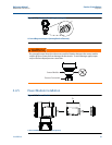
Three and five-valve configurations shown: