


48
Reference Manual
00809-0100-4102, Rev AA
Section 3: Installation
May 2013
Installation
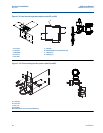
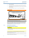
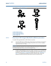
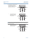
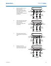
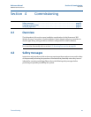
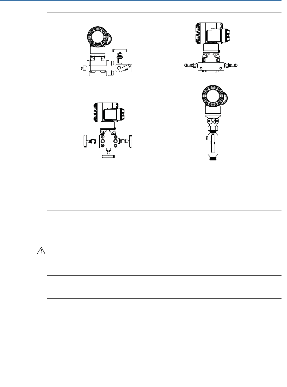
Figure 3-15. Integral Manifold Designs
A. 2051C and 304 Conventional
B. 2051C and 305 Integral Coplanar
C. 2051C and 305 Integral Traditional
D. 2051T and 306 In-Line
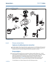
3.5.1 Rosemount 305 Integral Manifold installation procedure
To install a 305 Integral Manifold to a 2051 Wireless transmitter:
1. Inspect the PTFE sensor module O-rings. If the O-rings are undamaged, reusing them is
recommended. If the O-rings are damaged (if they have nicks or cuts, for example),
replace them with new O-rings.
Important
If replacing the O-rings, take care not to scratch or deface the O-ring grooves or the surface of
the isolating diaphragm while you remove the damaged O-rings.
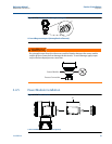
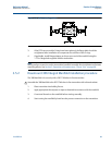
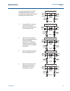
2. Install the Integral Manifold on the sensor module. Use the four 2.25-in. manifold bolts
for alignment. Finger tighten the bolts, then tighten the bolts incrementally in a cross
pattern as seen in Figure 3-16 on page 49 to final torque value. See “Flange bolts” on
page 37 for complete bolt installation information and torque values. When fully
tightened, the bolts should extend through the top of the module housing.
D
C
B
A