


4
Reference Manual
00809-0100-4102, Rev AA
Section 1: Introduction
May 2013
Introduction
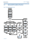
1.4 Transmitter overview
The Rosemount 2051C Coplanar design is offered for Differential Pressure (DP), Gage Pressure
(GP) and Absolute Pressure (AP) measurements. The Rosemount 2051C utilizes capacitance
sensor technology for DP and GP measurements. The Rosemount 2051T and 2051CA utilize
piezo-resistive sensor technology for AP and GP measurements.
The major components of the Rosemount 2051 Wireless transmitter are the sensor module and
the electronics housing. The sensor module contains the oil filled sensor system (isolating
diaphragms, oil fill system, and sensor) and the sensor electronics. The sensor electronics are
installed within the sensor module and include a temperature sensor, a memory module, and
the analog to digital signal converter (A/D converter). The electrical signals from the sensor
module are transmitted to the output electronics in the electronics housing. The electronics
housing contains the output electronics board, the antenna, and the battery. The basic block
diagram of the Rosemount 2051CD Wireless device is illustrated in Figure 1-3 on page 5.
For the Rosemount 2051, pressure is applied to the isolating diaphragm(s). The oil deflects the
sensor which then changes its capacitance or voltage signal. This signal is then changed to a
digital signal by the Signal Processing Module. The microprocessor then takes the signals from
the Signal Processing Module and calculates the correct output of the transmitter. This signal is
then sent via wireless communication to the Gateway.
An optional LCD can be ordered that connects directly to the output electronics board which
maintains direct access to the signal terminals. The display indicates output and abbreviated
diagnostic messages. A clear display cover is provided. For WirelessHART output, the LCD
Display features a three-line display. The first line describes the process variable measured, the
second line displays the measured value, and the third line displays engineering units. The LCD
can also display diagnostics messages.
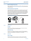
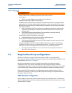
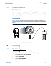
Note
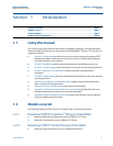
LCD Display utilizes a 3-line, 7-digit character display and can display output and diagnostic
messages. See Figure 1-2.
Figure 1-2. LCD Display
LCD Display