


6
Reference Manual
00809-0100-4102, Rev AA
Section 1: Introduction
May 2013
Introduction
Network design best practices
When mounting the device, recommended practices should be considered to achieve the best
wireless performance. See Appendix D: Network design best practices for more information on
recommended practices.
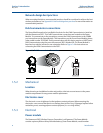
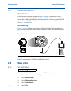
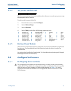
Field communicator connections
The Power Module needs to be installed in the device for the Field Communicator to interface
with the Rosemount 2051. The Field Communicator connections are located on the Power
Module. To communicate to the transmitter, connect the Field Communicator to the COMM
port connections on the Power Module. This transmitter uses the Green Power Module; please
order model number 701PGNKF. Field communication with this device requires a HART-based
Field Communicator using the correct Rosemount 2051 Wireless DD. The Power Module is
keyed and can only be inserted in one orientation. Refer to Figure 1-4 for instructions on
connecting the Field Communicator to the 2051.
Figure 1-4. Field Communicator Connections
1.5.2 Mechanical
Location
When choosing an installation location and position, take into account access to the power
module compartment for easy power module replacement.
Electronics cover
The electronics cover is tightened so that polymer contacts polymer. When removing the
electronics cover, ensure that there is no damage done to the o-ring. If damaged replace before
reattaching cover, ensuring polymer contacts polymer (i.e. no o-ring visible).
1.5.3 Electrical
Power module
The Rosemount 2051 Wireless Pressure Transmitter is self-powered. The Power Module
contains a primary lithium-thionyl chloride battery (Green Power Module, model number