43
Reference Manual
00809-0100-4102, Rev AA
Section 3: Installation
May 2013
Installation
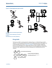
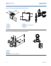
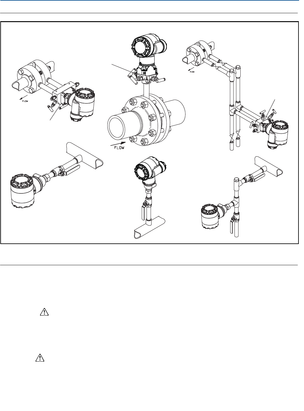
Figure 3-11. Installation examples
A. Drain/vent valves
3.4.3 Process connections
Coplanar or traditional process connection
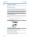
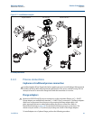
Install and tighten all four flange bolts before applying pressure to avoid leakage. When properly
installed, the flange bolts will protrude through the top of the sensor module housing. Do not
attempt to loosen or remove the flange bolts while the transmitter is in service.
Flange adapters
Rosemount 2051DP and GP process connections on the transmitter flanges are
1
/4–18 NPT.
Flange adapters are available with standard
1
/2–14 NPT Class 2 connections. The flange adapters
allow users to disconnect from the process by removing the flange adapter bolts. Use
plant-approved lubricant or sealant when making the process connections. Refer to
Dimensional Drawings on page 101 for the distance between pressure connections. This
distance may be varied ±
1
/4 in. (6.4 mm) by rotating one or both of the flange adapters.
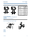
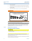
To install adapters to a Coplanar flange, perform the following procedure:
Liquid Service Gas Service Steam Service
A
A
A


