


44
Reference Manual
00809-0100-4102, Rev AA
Section 3: Installation
May 2013
Installation
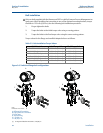
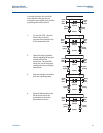
1. Remove the flange bolts.
2. Leaving the flange in place, move the adapters into position with the O-ring installed.
3. Clamp the adapters and the Coplanar flange to the transmitter module using the longer
of the bolts supplied.
4. Tighten the bolts. Refer to “Flange bolts” on page 37 for torque specifications.
Note
PTFE O-rings should be replaced if the flange adapter is removed.
Whenever you remove flanges or adapters, visually inspect the PTFE O-rings. Replace them if
there are any signs of damage, such as nicks or cuts. If you replace the O-rings, re-torque the
flange bolts after installation to compensate for cold flow. Refer to the process sensor body
reassembly procedure in Section 6: Troubleshooting on page 83.
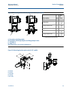
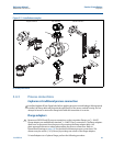
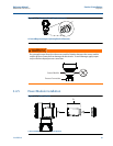
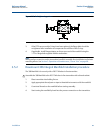
3.4.4 Inline process connection
Inline gage transmitter orientation
The low side pressure port on the inline gage transmitter is located in the neck of the
transmitter, behind the housing. The vent path is 360 degrees around the transmitter between
the housing and sensor (See Figure 3-12).
Keep the vent path free of any obstruction, such as paint, dust, and lubrication by mounting the
transmitter so that the process can drain away.
Interfering or blocking the atmospheric reference port will cause the transmitter to output
erroneous pressure values.
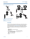
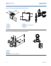
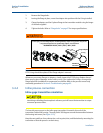
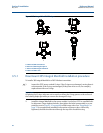
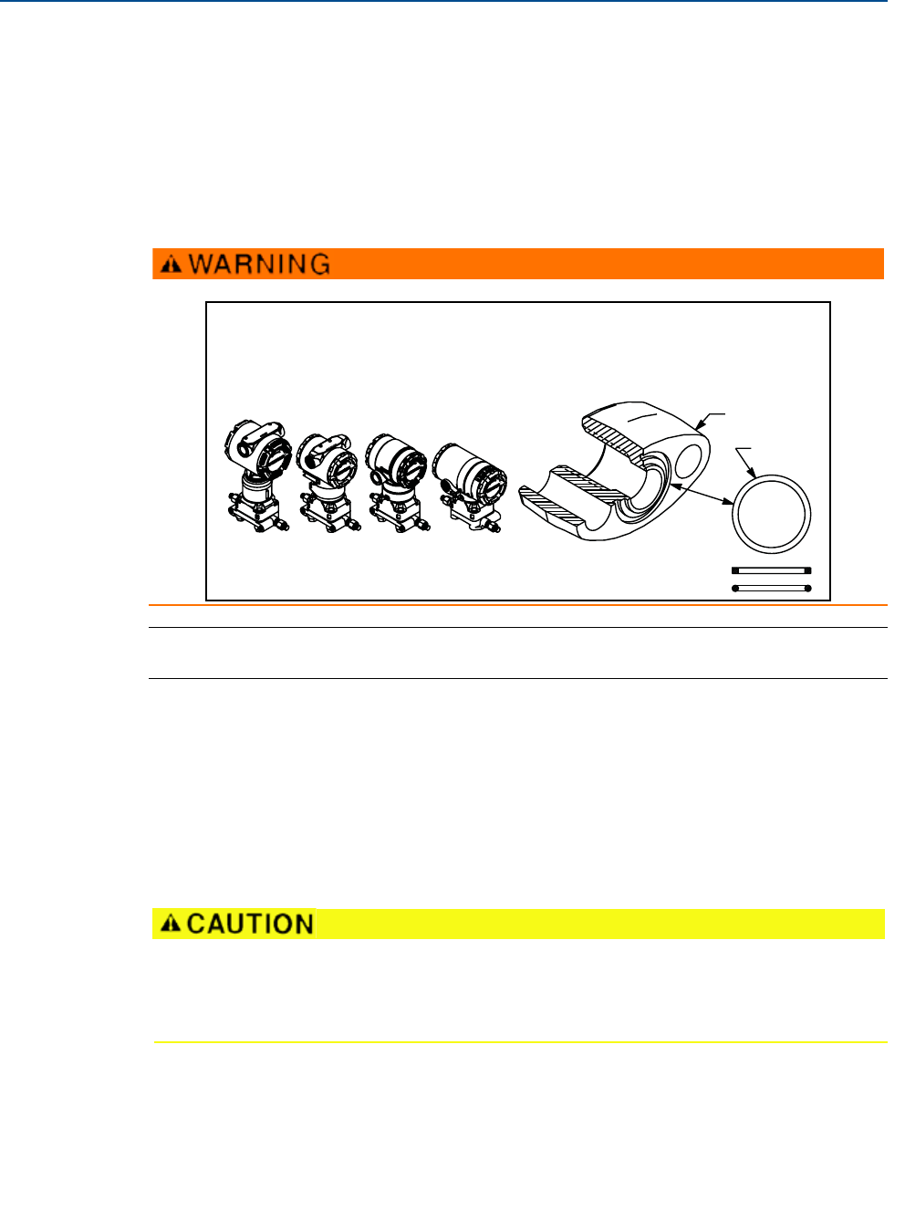
Failure to install proper flange adapter o-rings may cause process leaks, which can result in death or
serious injury. The two flange adapters are distinguished by unique o-ring grooves. Only use the
o-ring that is designed for its specific flange adapter, as shown below.
ROSEMOUNT 2051S / 2051 / 2051 / 3001 / 3095
Flange Adapter
O-ring
PTFE Based
Elastomer