


32
Reference Manual
00809-0100-4102, Rev AA
Section 3: Installation
May 2013
Installation
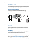
Internal antenna position
The internal antenna is designed for multiple mounting orientations. The transmitter should be
mounted according to measurement best practices for your pressure measurement application.
The antenna should be approximately 3 ft (1 m) from any large structure or building to allow
clear communication to other devices.
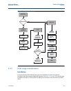
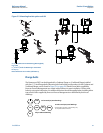
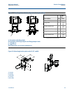
Field communicator connections
In order for the Field Communicator to interface with the Rosemount 2051 Wireless
Transmitter, the Power Module must be connected. Refer to Figure 3-1 for a diagram on how to
connect the Field Communicator.
Figure 3-1. Field Communicator Connections
3.3.3 Mechanical considerations
Steam service
For steam service or for applications with process temperatures greater than the limits of the
transmitter, do not blow down impulse piping through the transmitter. Flush lines with the
blocking valves closed and refill lines with water before resuming measurement. Refer to Figure
3-11 on page 43 for correct mounting orientation.
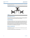
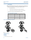
Side mounted
When the transmitter is mounted on its side, position the Coplanar flange to ensure proper
venting or draining. Mount the flange as shown in Figure 3-11 on page 43, keeping drain/vent
connections on the bottom for gas service and on the top for liquid service.
3.3.4 Environmental considerations
Best practice is to mount the transmitter in an environment that has minimal ambient
temperature change. The transmitter electronics temperature operating limits are –40 to 185 °F
(–40 to 85 °C). Refer to Appendix A: Specifications and Reference Data that lists the sensing
element operating limits. Mount the transmitter so that it is not susceptible to vibration and
mechanical shock and does not have external contact with corrosive materials.