53
Reference Manual
00809-0100-4102, Rev AA
Section 3: Installation
May 2013
Installation
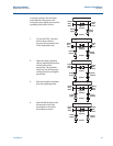
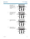
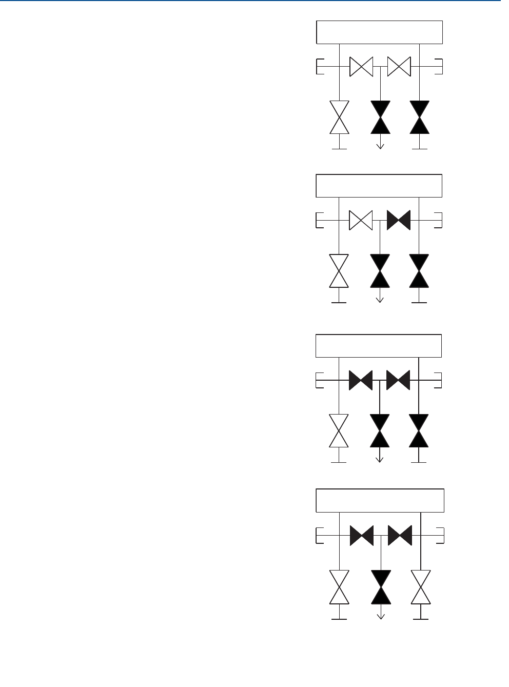
3. Open the equalize valve on
the low pressure
(downstream) side of the
transmitter. The manifold is
now in the proper
configuration for zeroing the
transmitter.
Test
(Plugged)
Test
(Plugged)
Equalize
(open)
Process
Isolate
(closed)
Isolate
(open)
H
L
Process
Equalize
(open)
Drain Vent
(closed)
Test
(Plugged)
Test
(Plugged)
Equalize
(closed)
Process
Isolate
(closed)
Isolate
(open)
H
L
4. After zeroing the transmitter,
close the equalize valve on
the low pressure
(downstream) side of the
transmitter.
Process
Equalize
(open)
Drain Vent
(closed)
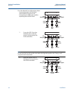
5. Close the equalize valve on
the high pressure (upstream)
side.
Test
(Plugged)
Test
(Plugged)
Equalize
(closed)
Process
Isolate
(closed)
Isolate
(open)
H
L
Process
Equalize
(closed)
Drain Vent
(closed)
6. Finally, to return the
transmitter to service, open
the low side isolation valve.
Test
(Plugged)
Test
(Plugged)
Equalize
(closed)
Process
Isolate
(open)
Isolate
(open)
H
L
Process
Equalize
(closed)
Drain Vent
(closed)


